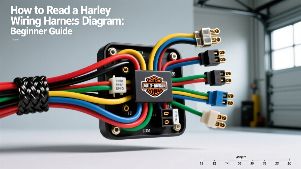
Introduction to Harley-Davidson Electrical Systems
For many motorcycle enthusiasts, opening a factory service manual and staring at a Harley wiring harness diagram feels like trying to read an alien language. However, Harley-Davidson electrical systems—whether on a classic Evolution Sportster or a modern Twin Cam touring model—are built on strict, logical fundamentals. Once you understand the standardized symbols, wire color codes, and circuit routing methods, tracing a fault or planning an aftermarket accessory install becomes a straightforward process.
This beginner-friendly guide will demystify the factory schematics. We will focus heavily on the widely wrenched 1999-2003 Sportster era as our baseline, as it represents the perfect bridge between vintage analog wiring and modern CAN-bus systems. By the end of this article, you will be able to trace a circuit from the battery to the ground, identify OEM connector types, and use a multimeter to diagnose voltage drops using the diagram as your roadmap.
Anatomy of a Harley Wiring Harness Diagram
Factory diagrams are not drawn to reflect the physical layout of the motorcycle. Instead, they are drawn to reflect the logical flow of electricity. Power sources (batteries, stators) are typically located at the top or left of the page, while grounds are routed to the bottom or right.
Standardized Symbols
- Ground Symbol: A horizontal line with three descending, shrinking vertical lines. This indicates a chassis ground. A circle with a minus sign indicates a direct battery ground.
- Splices (e.g., S104): Represented by a solid black dot where two or more wires intersect. This tells you that inside the harness loom, these wires are soldered and heat-shrunk together.
- Switches: Shown in their "normal" (unactuated) state. A headlight dimmer switch will be drawn in the "Low Beam" position until you physically click it.
- Connectors: Denoted by a bracket or a specific alphanumeric code (e.g., [1A] or [38B]). The letter 'A' usually denotes the male (pin) side, while 'B' denotes the female (socket) side.
Decoding the Wire Color Legend
Harley-Davidson uses a highly standardized, two-letter abbreviation system for wire colors. On a diagram, a wire labeled R/W means the primary color is Red (R) with a White (W) tracer stripe. Understanding this legend is the most critical step in using a Harley wiring harness diagram effectively.
| Abbreviation | Color | Standard Circuit Function |
|---|---|---|
| BK | Black | Ground / Earth Return |
| R | Red | Unswitched Battery Positive (Hot at all times) |
| O | Orange | Switched Ignition Power (Hot only when key is ON) |
| GY | Gray | Running Lights / Parking Lights / Instruments |
| W | White | Low Beam Headlight / Accessories |
| BE | Blue | High Beam Headlight |
| Y | Yellow | Turn Signals / Alternator Stator Output |
| G | Green | Tachometer Signal / Fuel Pump (Model dependent) |
Wire Gauge (AWG) and SAE Standards
When repairing or extending a harness, you must match the American Wire Gauge (AWG) specified in the manual. According to SAE J1128 standards, automotive and motorcycle wiring is rated based on thermal capacity and voltage drop over distance. Harley-Davidson predominantly uses GXL (General Cross-Linked) or TXL (Thin-wall Cross-Linked) wire for its harnesses due to the high engine bay temperatures and tight routing spaces.
- 10 AWG to 12 AWG: Used for main battery feeds, starter relays, and primary ground straps. Capable of handling 30A to 40A continuous loads.
- 14 AWG: The workhorse of the Harley harness. Used for headlight circuits, turn signals, and accessory feeds. Rated for up to 15A safely.
- 18 AWG: Used for low-draw sensor signals, LED indicator lights, and ECM data lines. Rated for roughly 3A to 5A.
Expert Tip: Never use standard PVC hardware-store wire for a motorcycle harness. PVC melts against the exhaust and becomes brittle under vibration. Always source SAE J1128 compliant GXL wire.
Step-by-Step: Tracing a Sportster Headlight Circuit
Let us apply this knowledge by tracing a common circuit on a 1999-2003 Sportster wiring harness diagram: the H4 Halogen Headlight.
- Power Source: Locate the Battery (BATT). Unswitched power flows via a 14 AWG Red (R) wire to the main fuse block.
- Ignition Switch: From the fuse, power flows to the Ignition Switch. When turned ON, it outputs Orange (O) switched power to the lighting circuit breaker.
- The Dimmer Switch: The Orange wire feeds into the left-hand grip dimmer switch. Here, the diagram shows a mechanical fork. If the switch is pushed down, power routes to the White (W) wire. If pushed up, it routes to the Blue (BE) wire.
- The Headlight Bucket (Connector [38]): The White and Blue wires travel through the handlebar harness and enter the headlight bucket via a 3-pin AMP Timer connector.
- Pin 1: Blue (High Beam Feed)
- Pin 2: White (Low Beam Feed)
- Pin 3: Black (Ground)
- Ground Return: The current passes through the tungsten filament of the H4 bulb and exits via the 14 AWG Black (BK) wire, which bolts directly to the frame behind the headlight bucket.
By following this logical path, you can isolate a failure. If the low beam is dead but the high beam works, the diagram tells you the ground (Pin 3) and the main power feed (Orange wire) are perfectly fine. The fault is isolated strictly to the White wire, the dimmer switch contacts, or the low-beam filament itself.
Common OEM Connectors and Pin Retention
A wiring diagram will reference connector codes, but it will not tell you how to physically extract a pin. Harley-Davidson relies heavily on a few key connector families:
- AMP Superseal / Timer: Common in headlight buckets and turn signals. These feature a secondary plastic wedge lock (TPA - Terminal Position Assurance). You must pry the TPA out before the metal release tab on the pin can be compressed for extraction.
- Deutsch DT Series: Used heavily in modern touring models and aftermarket harness kits for fuel injectors and ABS modules. These require a specialized insertion tool and feature a silicone grommet seal that must be pushed past the retention barb.
- Molex MX150: Found in newer ECM and sensor connections. Highly sealed against moisture but requires a specific micro-pick tool to depress the internal leaf-spring without damaging the wire crimp.
When repairing a harness kit, always use the correct open-barrel crimp tool. A proper 14 AWG crimp should withstand a pull-test of roughly 30 lbs before the wire breaks. Never use solder on crimp terminals in high-vibration motorcycle applications; solder wicks up the wire strands, creating a rigid stress point that will eventually snap under chassis vibration.
Troubleshooting Decision Tree Using the Diagram
When a component fails, use your Harley wiring harness diagram in conjunction with a digital multimeter (DMM) to perform a Voltage Drop Test. Continuity testing with the battery disconnected is useful, but it only tells you if a wire is broken. Voltage drop testing under a live load tells you if a wire has internal corrosion or high resistance.
The Voltage Drop Procedure
- Set your DMM to DC Volts.
- Turn the ignition ON and activate the failing circuit (e.g., turn on the high beam).
- Place the Red DMM probe on the positive battery terminal.
- Place the Black DMM probe on the power feed wire at the component (e.g., Pin 1 of the headlight connector).
- Interpretation: A healthy 14 AWG wire should show a voltage drop of less than 0.2V. If your meter reads 1.5V or higher, the diagram has just helped you pinpoint a corroded splice, a failing fuse block contact, or a frayed wire inside the loom.
- Repeat the test on the ground side: Red probe on the component ground pin, Black probe on the negative battery terminal. A drop over 0.1V on the ground side indicates a poor chassis ground. Clean the grounding ring terminal and apply dielectric grease to prevent future oxidation.
Essential Resources and Manuals
While this guide provides the foundational logic required to decode a Harley wiring harness diagram, you must always cross-reference your specific model year. A 2004 Sportster introduced a completely different ground-bussing system compared to the 2003 model year.
For authoritative connector specifications and wire standards, refer to the SAE J1128 Wiring Standards. Furthermore, investing in the official Harley-Davidson Electrical Diagnostic Manual for your specific VIN is non-negotiable for serious harness fabrication or deep-diagnostic troubleshooting. These manuals provide the exact pinout charts, connector face views, and splice location maps that aftermarket guides often omit.
Mastering the diagram transforms you from a parts-swapper into a true motorcycle electrician. Take your time, use painter's tape to mark your wires, and always let the schematic guide your multimeter probes.