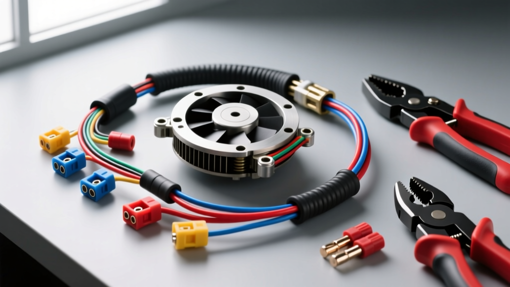
Understanding the 5.9L Cummins Fan Clutch Circuit
The 2003-2007 Dodge Ram equipped with the 5.9L ISB Common Rail Cummins engine utilizes an electro-viscous fan clutch assembly to manage engine cooling and reduce parasitic drivetrain loss. Unlike older purely mechanical clutches, this system relies on a 2-pin electrical connector to receive a 12V feed and an ECM-controlled ground path. When the Engine Control Module (ECM) demands maximum cooling, it completes the ground circuit, energizing the internal solenoid and locking the fan to the water pump shaft.
When the 5.9 Cummins fan clutch wiring harness degrades, the symptoms are immediate and severe. A broken ground wire prevents the clutch from engaging, leading to rapid engine overheating under load. Conversely, a short-to-ground on the control wire or internal solenoid failure can cause the fan to remain permanently locked, resulting in a deafening roar, severe power loss, and potential water pump bearing failure due to constant high-RPM drag. Replacing the harness with high-temperature, properly crimped components is the only reliable fix.
Why the OEM Harness Fails
The engine bay of the 3rd Generation Dodge Ram is a hostile environment for electrical components. The OEM fan clutch harness routes dangerously close to the exhaust manifold, the mechanical vacuum pump, and the radiator core. Over time, three primary failure modes destroy the factory wiring:
- Thermal Degradation: Standard PVC wire insulation becomes brittle after years of heat cycling, cracking and exposing bare copper.
- Chafing and Vibration: The 5.9L Cummins produces significant low-frequency vibration. If the factory split-loom rubs against the fan shroud or vacuum pump bracket, it eventually wears through to the conductors.
- Capillary Wicking: Once the connector seal degrades, moisture enters the terminal cavity. Through capillary action, water wicks up inside the wire insulation, turning the copper green (cupric oxide) several inches back from the connector. This high-resistance corrosion triggers P0480 (Cooling Fan 1 Control Circuit) codes.
Technical Specifications and Pinout Table
Before cutting any wires, it is critical to understand the circuit architecture. The 5.9L ISB fan clutch operates on a simple relay-fed, ECM-grounded logic. Below is the factory pinout specification for the 2003-2007 5.9L Common Rail fan clutch connector.
| Pin / Cavity | Function | OEM Wire Color | Recommended AWG | Signal Type |
|---|---|---|---|---|
| Pin A | 12V Solenoid Feed (from Relay) | Dark Green / Orange | 18 AWG TXL | +12V Switched |
| Pin B | ECM Control Ground | Black / Light Blue | 18 AWG TXL | Low-Side Driver (Ground) |
Note: Always verify wire colors with a multimeter against your specific model year's factory service manual, as mid-year production changes can occasionally alter tracer colors. The circuit logic, however, remains identical.
Required Tools and Materials
Do not attempt this repair with standard butt connectors and electrical tape. The under-hood environment requires automotive-grade materials. According to SAE J1128 Low Voltage Cable Specifications, standard PVC wire is insufficient for modern diesel engine bays.
- Wire: 18 AWG TXL (Cross-linked polyethylene) high-temperature automotive wire.
- Connector Kit: Delphi Weather-Pack 2-Pin Shroud and Tower with weather seals (Reference Delphi Automotive Connector Systems for terminal geometry).
- Crimping Tool: Weather-Pack specific open-barrel crimp tool (e.g., Sargent 1021-CT or equivalent).
- Sealing: Dual-wall adhesive-lined heat shrink (3M or Raychem).
- Protection: Tesa 51036 PET fleece harness tape and corrugated split loom.
- Chemicals: Dielectric silicone grease and electrical contact cleaner.
Step-by-Step Installation Guide
Step 1: Diagnostics and Safe Disconnect
Disconnect both negative battery cables to isolate the dual-alternator/battery setup on the 5.9L Cummins. Unplug the 2-pin connector at the fan clutch. Before removing the harness, use a multimeter to measure the resistance across the two pins on the fan clutch side (the component, not the harness). A healthy solenoid should read between 2.5 and 4.5 ohms at room temperature. If it reads open (OL) or shorted (0.0 ohms), the clutch assembly itself must be replaced alongside the harness.
Step 2: Harness Extraction and Wire Prep
Trace the OEM harness back toward the firewall and the main engine harness breakout. You must cut back past all visible corrosion. If the copper wire shows any green or black oxidation, cut further back until you reach bright, shiny copper. Stripping back a minimum of 6 to 8 inches from the connector is standard practice to ensure you are splicing into healthy metal. Strip 3/16-inch of insulation from both the chassis-side wires and your new 18 AWG TXL pigtail wires.
Step 3: Precision Crimping (Weather-Pack)
Weather-Pack terminals feature two distinct crimp zones: the conductor crimp and the insulation crimp. 1. Thread the silicone weather seal onto the wire before crimping. 2. Place the terminal in the correct cavity of the crimp tool (usually marked 18-20 AWG). 3. Crimp the conductor tabs tightly around the bare copper strands. 4. Crimp the insulation tabs around the TXL jacket to provide strain relief. Soldering is not recommended for high-vibration diesel applications, as it creates a stiff, brittle point that will eventually snap under engine harmonic vibration. A proper mechanical crimp is superior.
Step 4: Sealing and Loom Routing
Slide the adhesive-lined heat shrink over the splice points and apply heat until the adhesive oozes from the ends, creating a watertight seal. Push the weather seals into the back of the Weather-Pack connector tower until they click. Apply a dab of dielectric grease to the mating face of the connector to prevent moisture ingress and galvanic corrosion. Route the new harness away from the exhaust manifold and secure it to the factory bracket using zip-ties. Wrap the exposed wiring in Tesa fleece tape to eliminate rattling and provide abrasion resistance, then cover with split loom.
Troubleshooting Post-Installation
After reconnecting the batteries and starting the engine, verify the repair using the following decision tree:
- Symptom: Fan roars constantly at high RPM.
Cause: The ECM ground wire (Pin B) is shorted to chassis ground, or the fan clutch solenoid is internally shorted. Fix: Check Pin B for continuity to ground with the ECM unplugged. - Symptom: Engine overheats, fan never engages.
Cause: Loss of 12V feed or broken ground path. Fix: Check the Fan Clutch Relay in the TIPM (Totally Integrated Power Module) and verify 12V at Pin A with the engine running and A/C turned on. - Symptom: P0480 Code persists.
Cause: High resistance in the crimp or a failing ECM driver. Fix: Perform a voltage drop test across the harness while the circuit is active. A drop greater than 0.2V indicates a poor crimp connection.
For further diagnostic procedures and torque specifications for the fan clutch hub nut (typically 65 ft-lbs on the 5.9L ISB water pump shaft), consult resources like Geno's Garage Cummins Technical Articles or your factory Dodge/Cummins service manual.