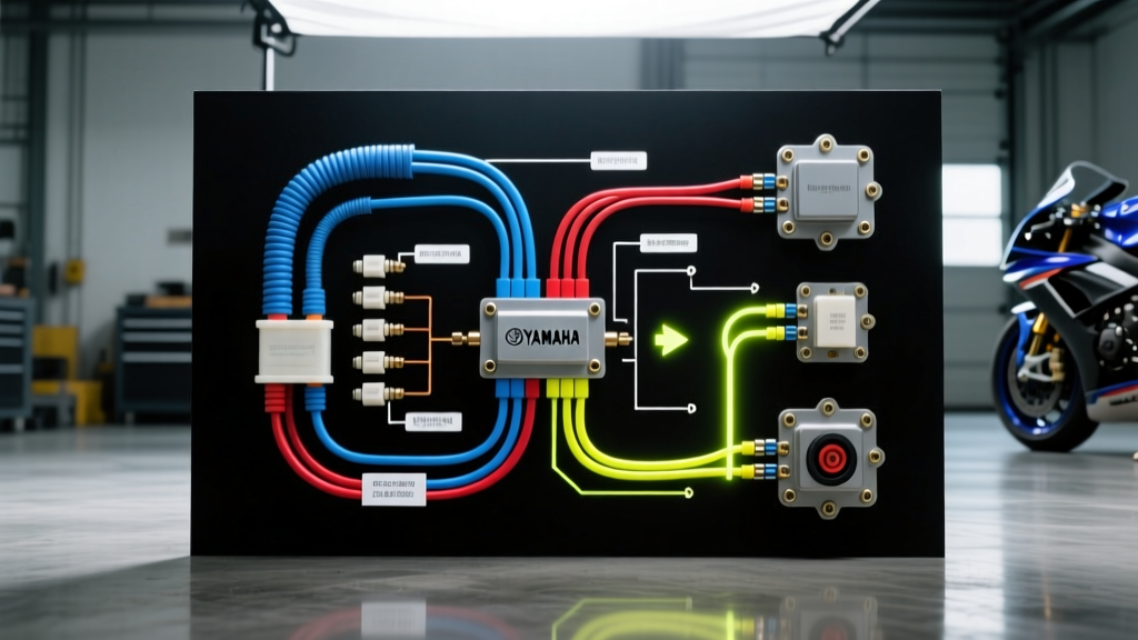
Understanding the Yamaha R1 Ignition Circuit Architecture
When diagnosing electrical gremlins or preparing a Yamaha YZF-R1 for dedicated track duty, the OEM ignition switch often becomes a primary point of failure or unnecessary weight. The Yamaha R1 ignition wiring diagram routes main battery power through the steering head switch before distributing it to the ECU, instrument cluster, and lighting circuits. Over time, the internal contacts of the OEM switch can suffer from carbon tracking, moisture ingress, or spring-fatigue, leading to intermittent stalling or total electrical blackouts while riding. For track-day enthusiasts, eliminating the heavy steering lock and ignition cylinder assembly saves roughly 1.8 lbs and removes a critical failure point. However, executing a proper bypass ignition switch Yamaha R1 ignition wiring diagram modification requires more than simply twisting wires together. A direct loop bypass defeats the handlebar-mounted engine stop switch, creating a severe safety hazard. This guide provides a comprehensive, step-by-step troubleshooting flow and a relay-integrated bypass procedure that maintains OEM safety protocols while eliminating the faulty key cylinder.
OEM Ignition Coupler Pinout & Wire Specifications
Before cutting or probing any wires, you must understand the chassis-side main ignition coupler. The 14B chassis (2009-2014) and early BX4 chassis utilize a primary 4-pin waterproof Sumitomo-style connector located just behind the steering stem. Japanese automotive wiring typically uses AVSS (Automotive Vinyl Sheath Thin-Wall) standards, which differ slightly from American AWG. Below is the definitive pinout for the main ignition harness.
| Pin | OEM Wire Color | Circuit Function | Wire Gauge (AVSS / AWG) | Fuse Protection |
|---|---|---|---|---|
| 1 | Red (R) | Constant +12V Battery Feed (Main Input) | 2.0mm² / 14 AWG | 30A Main Fuse |
| 2 | Brown (Br) | Switched IG Power (Dash, Lights, Horn) | 1.25mm² / 16 AWG | 10A IG Fuse |
| 3 | Red/White (R/W) | ECU Main Relay Trigger & Fuel Pump | 1.25mm² / 16 AWG | 15A ECU Fuse |
| 4 | Black/White (B/W) | Steering Lock Actuator / Ground Loop | 0.85mm² / 18 AWG | N/A |
Reference: For complete chassis-specific schematics, always cross-reference with the Yamaha Factory Service Documentation for your specific model year.
Step-by-Step Troubleshooting Flow: Is the Switch Failing?
Do not bypass the switch until you have definitively proven it is the root cause of the electrical fault. Use a digital multimeter (DMM) set to DC Voltage and Resistance to follow this decision tree.
Symptom 1: Intermittent Dash Flickering or Stalling Over Bumps
- Test: Set DMM to DC Voltage. Probe the Red (Pin 1) and Brown (Pin 2) wires at the chassis-side coupler with the key in the 'ON' position.
- Decision: If you read a steady 12.4V+ on Red, but the Brown wire fluctuates or drops below 11.5V when you wiggle the key, the internal IG contact plate is worn.
- Fix: Proceed to the relay-integrated bypass procedure below.
Symptom 2: Engine Cranks but ECU/Fuel Pump Does Not Prime
- Test: Probe the Red/White (Pin 3) wire with the key 'ON'. Check voltage at the ECU main relay trigger pin.
- Decision: If Pin 3 shows 0V but Pin 1 shows 12V, the internal ECU feed contact inside the ignition cylinder has failed or the inline 15A fuse is blown.
- Fix: Verify the fuse first. If the fuse is intact, the ignition switch is internally fractured. Bypass required.
Symptom 3: Parasitic Battery Drain While Parked
- Test: Remove the negative battery terminal. Connect DMM in series (Amps mode) between the negative post and the disconnected cable. Turn the key to 'OFF' and remove it.
- Decision: If the draw remains above 3mA, the ignition switch is failing to fully break the Red/White ECU circuit, or the steering lock actuator is shorting.
- Fix: Disconnect the 4-pin coupler. If the draw drops to <1mA, the ignition switch is shorted internally and must be bypassed or replaced.
Track-Safe Ignition Switch Bypass Procedure
A novice mistake is simply jumpering the Red, Brown, and Red/White wires together. This leaves the motorcycle permanently 'ON' whenever the battery is connected, bypassing the right-hand engine kill switch and risking ECU voltage spikes during alternator load dumps. The correct method uses a Bosch-style ISO mini relay (30A) triggered by the handlebar kill switch circuit.
Required Materials
- 1x Bosch-style ISO Mini Relay (12V, 30A)
- 1x Relay harness with flying leads
- 14 AWG and 16 AWG TXL primary wire (per SAE International J1128 Wire Standards)
- Adhesive-lined marine heat shrink (3:1 shrink ratio)
- Rosin-core solder and 45W+ soldering iron
Wiring Execution Steps
- Disconnect Power: Remove the negative battery terminal first to prevent ECU damage or short circuits.
- Prepare the Chassis Harness: Cut the chassis-side Red (Pin 1), Brown (Pin 2), and Red/White (Pin 3) wires approximately two inches from the OEM connector. Strip back 1/4 inch of insulation. Remove Pin 4 (Black/White) entirely and cap it, as the steering lock is being deleted.
- Wire the Relay Power Feed: Connect Relay Pin 30 to a new 14 AWG Red wire. Route this wire directly to the positive battery terminal, integrating an inline 30A MAXI fuse within 6 inches of the battery post.
- Wire the Relay Output: Connect Relay Pin 87 to the chassis-side Red (Pin 1) wire. This feeds raw battery power to the main harness when the relay closes.
- Bridge the Accessory Circuits: Solder the chassis-side Brown (Pin 2) and Red/White (Pin 3) wires directly to the Relay Pin 87 output wire. This ensures the dash and ECU receive power simultaneously when the relay is triggered.
- Integrate the Kill Switch Trigger: Locate the right-hand handlebar engine stop switch wiring (typically a Black/White and Black wire pair). Wire the relay coil ground (Pin 86) to a clean chassis ground. Wire the relay coil power (Pin 85) to the switched side of the engine stop switch. This ensures the main ignition relay only engages when the handlebar kill switch is in the 'RUN' position.
- Solder and Seal: Solder all connections. Do not rely on crimp connectors in the steering head area due to high vibration and moisture exposure. Slide 3:1 adhesive-lined heat shrink over every joint and apply heat until the adhesive purges from the ends.
Testing, Validation, and Reassembly
Once the relay-integrated bypass is complete, reconnect the battery negative terminal. The torque specification for the Yamaha R1 battery terminal bolts is strictly 5.5 Nm (4.0 ft-lbs); over-tightening will crack the lead posts and cause high-resistance starting faults.
Turn the handlebar kill switch to 'RUN'. You should hear an audible click from the ISO relay, followed by the instrument cluster illuminating and the fuel pump priming for exactly 3.0 seconds. Flip the kill switch to 'STOP'; the dash and fuel pump must immediately lose power. Finally, perform a voltage drop test across your new bypass wiring. With the engine running at 5,000 RPM, place your DMM probes on the battery positive post and the Red/White wire at the ECU coupler. A reading higher than 0.2V indicates excessive resistance in your bypass wire or a poor ground, requiring you to upgrade to a thicker 12 AWG feed wire. By following this exact troubleshooting flow and relay bypass methodology, you eliminate the fragile OEM steering lock mechanism while retaining a fully functional, track-legal safety cutoff.