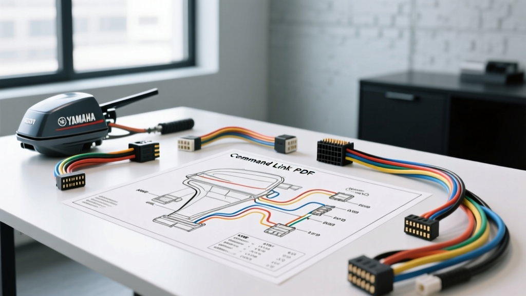
Navigating Yamaha Outboard Electrical Schematics
When diagnosing marine electrical faults, having the correct yamaha outboard wiring diagram pdf is not just a convenience; it is an absolute necessity. Marine environments subject electrical systems to severe galvanic corrosion, constant high-frequency vibration, and UV degradation. A generic automotive schematic will not account for the specialized tinned-copper wiring, waterproof Deutsch connectors, and isolated grounding systems required in outboard motors. This guide compares the primary sources for Yamaha wiring schematics and breaks down the technical differences between legacy analog harnesses and modern Command Link CAN bus networks, ensuring you select the exact documentation required for your specific engine series.
Comparing Diagram Sources: OEM vs. Aftermarket PDFs
Not all wiring diagrams are created equal. Depending on whether you are performing a simple gauge swap or a complete ECU harness rebuild, the source of your PDF will dictate your success rate.
1. Yamaha Official Service Manuals (OEM)
The gold standard for any marine technician is the official Yamaha Service Manual. These PDFs provide exhaustive, fold-out schematics that detail every splice, ground point, and ECU pinout. OEM diagrams are essential for troubleshooting the Digital Electronic Control (DEC) systems found on modern V6 and V8 outboards. They include specific multimeter testing procedures, expected voltage drops, and exact OEM harness part numbers. You can source these through authorized dealers or digital archives like Yamaha Outboard Parts, which maintain extensive microfiche and schematic libraries for legacy and current models.
2. Aftermarket Publishers (Seloc & Clymer)
Aftermarket manuals are excellent for mechanical teardowns and physical wire routing, but they often simplify complex electrical networks. For older carbureted or early EFI inline-4 engines (like the F115 or F150), Seloc PDFs provide highly readable, color-coded analog schematics. However, when dealing with Yamaha's proprietary Command Link network, aftermarket PDFs frequently reduce the entire CAN bus architecture to a generic 'network block,' rendering them useless for diagnosing communication dropout codes or backbone voltage faults.
3. Community Repositories & Forum PDFs
Marine communities and forums like Marine Engine or The Hull Truth often host user-uploaded PDFs. While these are invaluable for finding real-world modifications, aftermarket gauge integrations, and community-discovered fixes for notorious chafe points, they carry the risk of containing outdated or modified schematics. Always cross-reference forum-sourced PDFs with an OEM baseline before cutting or splicing any wires.
Generational Wiring Shift: Analog vs. Command Link
When searching for your specific diagram, you must identify your engine's generation. Yamaha's transition from discrete analog signaling to the Command Link digital network fundamentally changed the wiring architecture.
Legacy Analog Harnesses (Pre-2010 F-Series)
Older Yamaha outboards utilize a discrete wire for every single function. The tachometer receives a raw AC pulse directly from the stator's dedicated charge coil. The fuel gauge relies on a variable resistance sender (typically 33-240 Ohms). Troubleshooting these systems requires a standard multimeter and a thorough understanding of the 14-pin main engine connector.
Command Link & CAN Bus Architecture (Modern F-Series, V6, V8)
Modern Yamaha outboards utilize a Controller Area Network (CAN bus) to transmit data. Instead of running 15 individual wires from the engine to the helm, the ECU digitizes all sensor data and sends it over a single twisted-pair backbone cable. When reviewing a Command Link wiring diagram PDF, you will notice the absence of discrete gauge wires. Instead, you will see:
- Backbone Cables: The main data highway running from the engine to the helm.
- Drop Cables: Short spur lines connecting individual gauges or the main harness to the backbone via T-fittings.
- Terminating Resistors: Crucial 120-ohm resistors placed at both physical ends of the backbone to prevent signal reflection and data corruption.
Technical Reference: Yamaha 14-Pin Main Harness Connector
For legacy and many modern non-DEC engines, the 14-pin round connector is the primary interface between the outboard and the boat's helm wiring. Below is the standard pinout and wire color matrix based on OEM specifications. Always verify against your specific engine's PDF, as high-horsepower models may utilize an 18-pin variant.
| Pin | Wire Color | Function | AWG / Spec | Diagnostic Notes |
|---|---|---|---|---|
| 1 | Red | Battery +12V (Memory/ECU) | 10 AWG | Must have < 0.2V drop from battery post. |
| 2 | Black | Main Ground | 10 AWG | Check for galvanic corrosion at the engine block ring terminal. |
| 3 | Yellow | Stator Charge Coil Output | 12 AWG | Outputs raw AC voltage to the rectifier/regulator. |
| 4 | Green | Tachometer Signal | 14 AWG | Carries AC pulse from stator; verify with oscilloscope or AC multimeter. |
| 5 | Pink | Fuel Level Sender | 14 AWG | Variable resistance; check for chafing against the fuel tank. |
| 6 | Brown | Overheat / Alarm Output | 14 AWG | Grounds out to trigger the helm warning horn. |
| 7 | White | Trim Sender Signal | 14 AWG | Variable resistance from the trim cylinder sender unit. |
| 8 | Light Green | Trim Up (Relay Trigger) | 12 AWG | Carries +12V to the trim relay solenoid. |
| 9 | Blue | Trim Down (Relay Trigger) | 12 AWG | Carries +12V to the trim relay solenoid. |
| 10 | Orange | PTT Ground / Accessory | 12 AWG | Provides dedicated ground path for high-draw trim motors. |
| 11 | Black/White | Ignition Stop (Kill) | 14 AWG | Grounding this wire shorts the CDI/ECU to stop spark. |
Battery Cable AWG & Routing Specifications
A common failure point in outboard electrical systems is undersized battery cabling. Marine engines draw massive amperage during cranking (often exceeding 250 amps on V6 models). According to SAE J1171 and ABYC marine standards, you must use stranded, tinned copper wire. Never use solid copper automotive wire, as it will rapidly corrode and snap under engine vibration. Select your cable gauge based on the total round-trip distance from the battery to the engine ground stud.
| Engine HP Class | Run Length (Under 15 ft) | Run Length (15 - 20 ft) | Run Length (Over 20 ft) |
|---|---|---|---|
| 90HP - 150HP (Inline 4) | 4 AWG | 2 AWG | 1/0 AWG |
| 175HP - 250HP (V6) | 2 AWG | 1/0 AWG | 2/0 AWG |
| 300HP+ (V8 / Supercharged) | 1/0 AWG | 2/0 AWG | 4/0 AWG |
Diagnostic Workflows Using the PDF
Once you have secured the correct Yamaha outboard wiring diagram PDF, use it to execute systematic diagnostic tests. The most common electrical failure in marine outboards is the stator/rectifier assembly.
1. Stator AC Output Test
Locate the yellow wires originating from the stator on your schematic. Disconnect the main harness and set your multimeter to AC Volts. Crank the engine or let it idle. You should read a minimum of 18V AC at idle, scaling up to 50V+ AC at 3000 RPM. If one phase reads significantly lower, the stator winding is shorted internally.
2. Rectifier/Regulator DC Output Test
Follow the yellow wires on your PDF into the rectifier/regulator module. Switch your multimeter to DC Volts. With the engine running at 2000 RPM, measure the DC output at the battery terminals. It must read between 13.8V and 14.4V. If the voltage exceeds 15V, the regulator has failed and is actively boiling the battery electrolyte and risking ECU damage. If it reads below 13.2V, check the black ground wire from the rectifier to the engine block for hidden corrosion.
3. Command Link Network Resistance Test
For CAN bus systems, turn the key OFF. Disconnect the battery to prevent back-feeding. Locate the backbone drop cable at the helm gauge. Set your multimeter to Ohms and measure across the CAN High and CAN Low pins (refer to your specific DEC diagram for pin locations, typically Pins A and B on the 6-pin Deutsch connector). A healthy, properly terminated network will read exactly 60 ohms (two 120-ohm resistors in parallel). A reading of 120 ohms indicates a missing terminator; a reading of near 0 ohms indicates a shorted backbone cable.
Conclusion
Selecting the right yamaha outboard wiring diagram pdf requires matching the document to your specific engine generation, horsepower class, and network architecture. Rely on OEM service manuals for ECU and CAN bus diagnostics, and utilize aftermarket guides for physical routing and mechanical integration. Always adhere to SAE J1171 marine standards regarding tinned copper AWG sizing, and utilize the 14-pin matrix and diagnostic workflows provided above to isolate faults efficiently and safely on the water.