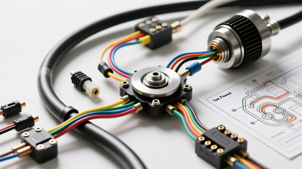
Introduction to the Toro Z-Master 12V Electrical Architecture
Commercial zero-turn mowers operate in some of the most demanding, high-vibration, and debris-heavy environments in the automotive and landscaping sectors. When consulting the wiring diagram for Toro Z Master models—particularly those equipped with 60-inch or 72-inch decks and Kawasaki FX or Kohler Command PRO engines—it becomes immediately clear that the 12V DC electrical system is far more complex than a standard lawn tractor. The system must manage high-amperage starter circuits, stator-driven charging systems, electromagnetic Power Take-Off (PTO) clutches, and a stringent Safety Interlock Module (SIM).
This practical how-to installation guide focuses on the most critical and failure-prone electrical subsystems on the Z-Master: the PTO clutch engagement circuit and the operator-presence safety interlocks. Whether you are replacing a burned-out Ogura PTO clutch, upgrading to a heavy-duty Warner Electric unit, or troubleshooting a parasitic draw caused by a failing interlock relay, understanding the precise wire color codes, AWG requirements, and relay pinouts is mandatory for a reliable repair.
Wire Specifications and OEM Color Codes
Before cutting, crimping, or routing any new wires, you must adhere to strict gauge and insulation requirements. The engine bay of a Z-Master routinely exceeds 250°F (121°C) near the exhaust manifolds. Standard PVC-jacketed wire will melt and short out against the chassis. Per the SAE J1128 Standard for low-tension primary cables, you must use Cross-Linked Polyethylene (XLPE) or Tefzel (ETFE) insulated wire for any harness routed within 12 inches of the engine block.
Z-Master Electrical Specification Chart
| Circuit Function | OEM Wire Color | Minimum AWG | Connector Type | Operating Parameters |
|---|---|---|---|---|
| Main Battery Feed | Red | 6 AWG | Ring Terminal (3/8') | Continuous 30A+, Peak 250A (Cranking) |
| Chassis Ground | Black | 6 AWG | Ring Terminal (3/8') | Must bond to bare, unpainted frame steel |
| PTO Clutch Feed | Purple | 10 AWG | Weather-Pack 2-Pin | Steady 4.5A, Inrush 15A |
| Ignition 'Run' Circuit | White | 14 AWG | Spade / Packard 56 | Switched 12V+ (Ignition ON) |
| Seat Switch / Operator | Gray | 16 AWG | Deutsch DT 2-Pin | Normally Open (Closed when seated) |
| PTO Dash Switch | Green | 16 AWG | Packard 56 Female | Switched 12V+ to Relay Pin 86 |
Step-by-Step PTO Clutch and Interlock Installation
Replacing the PTO clutch and integrating it into the Z-Master's safety interlock logic requires methodical execution. A common mistake made by field technicians is wiring the PTO clutch directly to the dash switch. The dash switch is rated for a maximum of 5 amps; the electromagnetic clutch's inrush current will rapidly carbonize the switch contacts, leading to voltage drop and premature clutch burnout. You must use a heavy-duty relay.
Step 1: Harness Routing and Thermal Protection
Begin by disconnecting the negative battery terminal and isolating it with a non-conductive boot. Route the new 10 AWG Purple PTO feed wire from the main relay block to the front of the mower deck.
- Clearance: Maintain a minimum 4-inch clearance from the Kawasaki FX exhaust headers.
- Chafe Protection: Where the harness passes through the front deck bulkhead, install a rubber grommet and apply marine-grade dielectric grease to prevent moisture ingress.
- Crimping: Follow IPC/WHMA-A-620 Crimp Standards. Use an open-barrel crimp tool for Weather-Pack terminals, ensuring the wire brush is visible just past the terminal bellmouth. Seal the connection with dual-wall, adhesive-lined heat shrink tubing.
Step 2: Safety Interlock Module (SIM) Logic and Wiring
The Toro Z-Master utilizes a sequential logic gate to prevent the engine from cranking if the PTO is engaged, and to kill the engine if the operator leaves the seat while the PTO is active. If you are bypassing a failed SIM for diagnostic purposes or wiring a replacement universal interlock relay block, you must understand the circuit path.
The starter solenoid ground path (or trigger path, depending on the specific Z-Master year and engine package) is routed through the PTO microswitch.
- Brake/Neutral Switch: Must be closed (levers in the outward, neutral/parked position).
- PTO Microswitch: Must be in the 'Disengaged' position (circuit closed to ground).
- Seat Switch: If the PTO is engaged, the circuit relies on the Gray seat switch wire remaining closed to ground. If the circuit opens (operator stands up), the ignition module's ground path is severed, killing the spark.
Step 3: PTO Clutch Relay and Flyback Diode Integration
Install a standard Bosch-style 12V 40A automotive relay in a dry, elevated location on the chassis. Wire the relay as follows:
- Pin 30 (Common): Connect to a fused 12V+ source directly from the battery side of the main solenoid using 10 AWG Red wire. Install an inline 15A MAXI fuse.
- Pin 87 (Normally Open): Connect to the Purple 10 AWG wire leading to the PTO clutch.
- Pin 86 (Coil +): Connect to the Green wire from the PTO dash switch (switched 12V+).
- Pin 85 (Coil -): Connect to a clean chassis ground using 14 AWG Black wire.
Real-World Troubleshooting: Voltage Drop and Clutch Air Gap
If the newly installed PTO clutch slips, overheats, or fails to engage, do not immediately assume the component is defective. According to the Toro Commercial Service Portal, over 70% of premature PTO failures are caused by improper air gap or systemic voltage drop.
The Voltage Drop Test
With the engine running at 3200 RPM (operating speed) and the PTO engaged, use a digital multimeter to measure voltage directly at the Weather-Pack connector on the clutch.
- Acceptable: 13.8V to 14.2V DC.
- Failing: Below 12.5V DC.
Setting the Mechanical Air Gap
Electrical wiring is only half the battle. The mechanical air gap between the PTO rotor and the armature must be set precisely using a feeler gauge.
- Insert a 0.015-inch feeler gauge through the inspection slots in the clutch housing.
- Adjust the three perimeter lock-nuts until you feel a slight drag on the gauge.
- Tighten the lock-nuts to the manufacturer's specified torque (typically 12-15 ft-lbs).
Summary of Best Practices
Wiring a commercial zero-turn mower requires the same discipline as wiring a heavy-duty diesel truck. By adhering to SAE wire standards, utilizing proper relay logic to protect low-amperage dash switches, installing flyback diodes to protect sensitive charging stators, and meticulously sealing connections against moisture and vibration, your Toro Z-Master will deliver thousands of hours of reliable, spark-free operation.