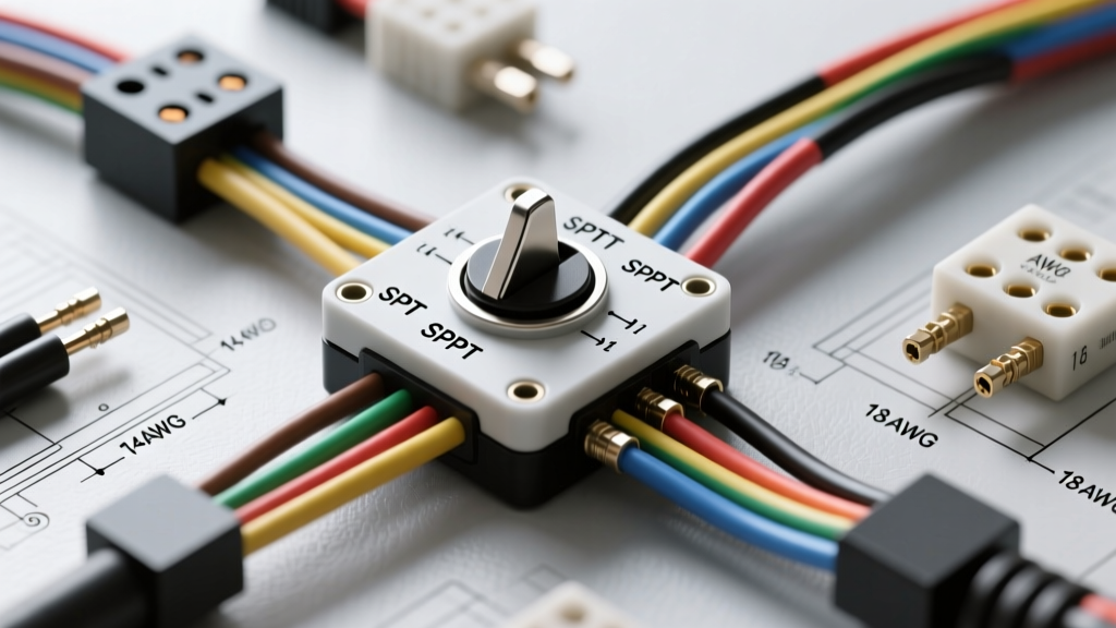
Introduction to Automotive Toggle Switch Topologies
When designing auxiliary circuits for off-road vehicles, heavy-duty trucks, or custom marine applications, selecting the correct switch topology is critical for both safety and reliability. A standard wiring diagram toggle switch reference must account for inductive loads, environmental sealing, and precise terminal pinouts. Unlike standard residential switches, automotive toggle switches must withstand high-frequency vibration, extreme temperature fluctuations, and 12V/24V DC arcing. This technical specification guide details the mechanical configurations, wire gauge requirements, and relay integration strategies necessary for professional-grade vehicle electrical systems.
Standard Toggle Switch Configurations & Terminal Pinouts
Toggle switches are categorized by their poles (the number of separate circuits they control) and throws (the number of positions the actuator can connect to). Understanding these configurations is the first step in interpreting any automotive wiring diagram toggle switch schematic.
| Switch Type | Pole/Throw | Terminal Count | Common Automotive Application | Terminal Style |
|---|---|---|---|---|
| SPST | 1P / 1T | 2 (or 3 for LED) | Basic auxiliary lights, horn, fuel pump | 1/4' Blade or #8 Screw |
| SPDT | 1P / 2T | 3 | Dual-speed fans, On-Off-On accessory control | 1/4' Blade |
| DPST | 2P / 1T | 4 | Simultaneous dual-circuit cutoff, marine battery isolation | #8 Screw |
| DPDT | 2P / 2T | 6 | Winch in/out control, power window polarity reversal | 1/4' Blade or PCB Mount |
SPST (Single Pole Single Throw) Wiring Specifications
The SPST switch is a simple two-position (On/Off) device. In a standard non-illuminated configuration, Terminal 1 receives switched or unswitched 12V power from the fuse panel, and Terminal 2 routes the load to the accessory.
Illuminated SPST Variants: Many off-road SPST switches feature an internal LED or neon indicator. These require a third terminal. In dependent illumination designs, the third terminal must be grounded, and the LED only illuminates when the load circuit is complete. In independent designs, the third terminal receives a separate 12V feed from the instrument panel dimmer circuit, allowing the switch to illuminate when the headlights are on, regardless of the switch position. Always verify the internal resistor configuration before applying 12V to the illumination pin to prevent burning out the indicator diode.
SPDT (Single Pole Double Throw) Wiring Specifications
The SPDT switch features three terminals and is typically configured as On-Off-On or On-None-On. The center terminal is the 'Common' (C) input. The top and bottom terminals are the 'Normally Open' (NO) and 'Normally Closed' (NC) outputs. In automotive cooling fan wiring diagrams, the center terminal receives 12V power. Throwing the switch up routes power to the low-speed relay coil, while throwing it down routes power to the high-speed relay coil. The center-off position breaks the circuit entirely.
DPDT (Double Pole Double Throw) Polarity Reversal Wiring
The DPDT switch is essential for controlling DC motor direction, such as in winch solenoid triggers, bed lifts, or power tailgates. It features six terminals, effectively acting as two synchronized SPDT switches. To achieve polarity reversal (often called an H-Bridge configuration in solid-state electronics), the terminals must be cross-wired:
- Power Input: 12V+ enters the top-center terminal; Ground enters the bottom-center terminal.
- Cross-Wiring: A jumper wire connects the Top-Left terminal to the Bottom-Right terminal. A second jumper connects the Bottom-Left terminal to the Top-Right terminal.
- Motor Output: The motor leads connect to the left-center and right-center terminals.
When the actuator is flipped, the polarity across the center output terminals reverses, instantly changing the rotational direction of the DC motor. According to Littelfuse engineering specifications, DPDT switches used for motor reversal must feature Silver Cadmium Oxide (AgCdO) contacts to resist the severe inductive arcing generated by DC motor back-EMF.
Wire Gauge (AWG) and Current Rating Specifications
Matching the wire gauge to the switch's amperage rating and the specific load is critical to preventing voltage drop and thermal melting of the switch housing. The following table outlines standard SAE J1128 primary cable sizing for 12V DC toggle switch circuits, assuming a standard 10-foot round-trip wire run.
| Max Continuous Load | Minimum AWG Size | Recommended Inline Fuse | Minimum Switch Rating |
|---|---|---|---|
| 5 Amps | 18 AWG | 7.5A Mini | 10A @ 12VDC |
| 10 Amps | 16 AWG | 15A Mini | 15A @ 12VDC |
| 15 Amps | 14 AWG | 20A ATO | 20A @ 12VDC |
| 20 Amps | 12 AWG | 25A ATO | 30A @ 12VDC |
| 30+ Amps | 10 AWG or 8 AWG | 40A MAXI | Use ISO Relay (See Below) |
SAE Automotive Wire Color Codes for Auxiliary Switches
While custom harness builders often use their own color schemas, adhering to established automotive standards ensures that future technicians can safely troubleshoot the vehicle. Based on standard OEM and Painless Performance wiring conventions, the following color codes should be applied to toggle switch circuits:
- Red: Unswitched, fused 12V+ battery power feeding the switch input terminal.
- Blue: Switched 12V+ output running from the switch to the accessory or relay coil.
- Black: Dedicated chassis ground for illuminated switch indicators or relay coils.
- Yellow: High-current switched power (typically used for heavy auxiliary lighting arrays).
- Orange: Instrument panel dimmer feed (used for independent switch illumination circuits).
- White: Low-beam or secondary circuit trigger in SPDT headlight rocker configurations.
Relay Integration: Protecting the Toggle Switch Contacts
A common and dangerous mistake in aftermarket vehicle wiring is routing high-amperage loads directly through a dashboard toggle switch. Standard panel-mount toggle switches are typically rated for 15A to 20A. However, inductive loads like HID ballasts, large cooling fans, and winch contactors can draw 40A to 80A during initial inrush. Routing this current through a standard toggle switch will cause severe contact arcing, melting the internal phenolic resins and potentially causing an electrical fire.
The Solution: Use the toggle switch exclusively as a low-current trigger for a standard Bosch-style ISO Mini Relay.
- Pin 86: Connect to the toggle switch output (Terminal 2).
- Pin 85: Connect to a clean chassis ground.
- Pin 30: Connect to heavy-gauge (10 AWG or 8 AWG) fused battery power.
- Pin 87: Connect to the high-draw accessory load.
This configuration ensures that the toggle switch only carries the relay coil current (typically 150mA to 300mA), vastly extending the mechanical life of the switch and eliminating voltage drop at the dashboard.
Troubleshooting Common Toggle Switch Failures
When an auxiliary circuit fails, the toggle switch is often the primary suspect. Use the following diagnostic decision tree to isolate the fault:
Symptom: Accessory receives power, but dims or flickers when the switch is toggled.
- Cause: Carbon tracking or pitting on the internal copper/silver contacts due to prolonged inductive arcing.
- Diagnostic Test: Perform a millivolt drop test. Set a digital multimeter to DC mV. Place the red probe on the switch input terminal and the black probe on the output terminal while the circuit is under load. A healthy switch will read less than 100mV (0.1V). A reading above 300mV indicates excessive internal resistance.
- Fix: Replace the switch. Do not attempt to clean sealed automotive toggle switches with contact cleaner, as this will wash away the factory dielectric grease.
Symptom: Switch actuator feels loose, and the circuit drops out over bumps.
- Cause: Terminal nut back-out due to high-frequency chassis vibration, common in off-road and heavy-duty truck applications.
- Diagnostic Test: Inspect the #8-32 terminal nuts on the rear of the switch. Check for heat discoloration on the spade connectors, which indicates a loose connection causing localized resistance.
- Fix: Re-terminate the wires using closed-loop ring terminals. Apply a drop of blue Loctite 242 to the threads and torque the terminal nuts to exactly 8-12 in-lbs per SAE J2191 vibration standards. Use external tooth lock washers between the terminal and the nut.
Symptom: Illuminated LED indicator remains lit even when the switch is in the OFF position.
- Cause: Incorrect grounding of a dependent-illumination SPST switch. If the load side of the circuit has a secondary ground path (such as a relay coil or a solid-state module with internal bleed resistors), a tiny amount of current will bypass the open switch contacts, illuminating the high-efficiency LED.
- Fix: Install a 10k-ohm, 1/2-watt bleeder resistor in parallel with the load to drain the residual ghost voltage, or switch to an independent-illumination toggle switch that relies on a dedicated ground pin rather than the load circuit.
Environmental Sealing Considerations
When mounting toggle switches on the exterior of a vehicle, on a roll cage, or in an open marine environment, standard interior switches will fail rapidly due to moisture ingress and UV degradation. Always specify switches with an IP67 or IP68 rating, featuring silicone boot seals and O-ring face gaskets. For extreme environments, look for MIL-DTL-3950 certified switches, which are tested for salt spray resistance and thermal shock cycling from -65°C to +160°C.