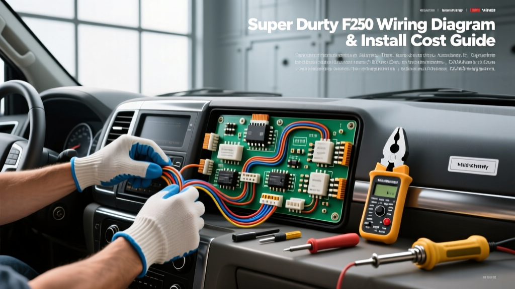
The Reality of Modern F-250 Stereo Integration
When evaluating a super duty ford f250 stereo wiring diagram, it is critical to understand that late-model trucks (2017-present) no longer rely on simple 12-volt power, ground, and analog speaker wires. The integration of the SYNC 3 and SYNC 4 infotainment systems means the radio acts as a gateway module on the vehicle's High-Speed Controller Area Network (HS-CAN). Upgrading the stereo in an F-250 Super Duty requires a meticulous cost and tool requirements analysis to avoid triggering Body Control Module (BCM) faults, parasitic battery drains, or disabling the Passive Anti-Theft System (PATS).
This guide breaks down the exact tooling, financial investment, and technical specifications required to safely interpret and execute a Super Duty stereo wiring schematic without compromising the truck's multiplexed data networks.
Tool Requirements Analysis: Beyond the Basics
Standard wire strippers and electrical tape are insufficient—and potentially destructive—when working with Ford's data-bus lines. The following tools are mandatory for a professional-grade installation.
Essential Diagnostic & Splicing Tools
- True RMS Digital Multimeter (DMM): A high-quality DMM (such as the Fluke 87V) is required to verify CAN-bus voltages. You must confirm that the CAN-H line operates between 2.5V and 3.5V, and the CAN-L line operates between 1.5V and 2.5V relative to chassis ground. Standard test lights will short the data bus and throw U-codes.
- Precision Wire Strippers: Ford utilizes 18 AWG and 20 AWG stranded copper for data and low-current accessory lines. Using heavy-duty strippers calibrated for 12 AWG will sever the copper strands, increasing resistance and causing data packet loss. Use automatic strippers calibrated specifically for 18-24 AWG wire.
- Posi-Tap Connectors or Military Splices: Never use standard 'T-Taps' on an F-250's CAN-bus or 12V memory lines. T-Taps rely on a blade that cuts through the wire strands, creating a high-resistance point prone to oxidation and vibration failure. Use Posi-Taps (which twist around the wire without severing strands) or perform a Western Union splice followed by soldering and adhesive-lined heat shrink.
- Automotive Panel Removal Kit & 7mm Socket: The F-250 center stack bezel is secured by hidden 7mm bolts and high-tension plastic clips. Prying without the correct nylon tools will mar the soft-touch dashboard materials.
Cost Breakdown: OEM Harness vs. Data-Bus Interfaces
A common mistake among DIY installers is purchasing a $15 generic wiring harness from an online marketplace, only to realize it lacks the data-bus integration required for the F-250. Below is a realistic cost analysis for a proper, reliable installation.
| Component / Tool | Estimated Cost | Purpose & Technical Justification | Risk of Skipping / Cheap Alternative |
|---|---|---|---|
| Data-Bus Interface (e.g., iDatalink Maestro RR2) | $175 - $220 | Translates Ford HS-CAN data into analog signals for steering wheel controls (SWC), backup camera, and accessory 12V turn-on. | Loss of SWC, climate data on screen, and potential PATS immobilizer engagement. |
| OEM-Specific Radio Harness (24-Pin/36-Pin) | $45 - $80 | Provides a plug-and-play connection to the factory bulkhead connector without cutting OEM wires. | Splicing directly into the truck's bulkhead voids warranties and risks BCM damage. |
| Posi-Tap / Posi-Lock Connector Kit | $15 - $25 | Ensures vibration-proof, oxidation-free splices for 18 AWG data and 12 AWG power lines. | Intermittent radio reboots, CAN-bus U-codes, and parasitic battery drains. |
| Adhesive-Lined Heat Shrink (Dual Wall) | $15 | Seals splices against moisture and humidity, crucial for trucks used in off-road or marine environments. | Green corrosion on copper strands leading to high-resistance voltage drops. |
Total Estimated Wiring & Integration Cost: $250 - $340 (excluding the head unit and labor).
Super Duty Ford F250 Stereo Wiring Diagram: Core Pinouts
The 2017-2022 Ford F-250 Super Duty with SYNC 3 typically utilizes a 24-pin primary connector for power, ground, data, and front audio, alongside a separate LVDS cable for the touchscreen and a secondary connector for rear audio and amplifiers. Below is the critical pinout data for the primary 24-pin harness. Always verify with a DMM before making connections, as Ford occasionally revises wire colors mid-production cycle.
24-Pin Connector Specification Chart (SYNC 3 / 4 Base Audio)
| Pin # | Wire Color | Function | AWG | Verification Method |
|---|---|---|---|---|
| 1 | White/Blue | HS-CAN High (+) | 18 | DMM: 2.5V - 3.5V (Key ON) |
| 2 | White | HS-CAN Low (-) | 18 | DMM: 1.5V - 2.5V (Key ON) |
| 6 | Yellow/Red | 12V Constant Battery | 12 | DMM: 12.2V - 12.6V (Key OFF) |
| 24 | Black/Green | Chassis Ground | 12 | Continuity to chassis (< 0.5 Ohms) |
| 3 | White/Red | MS-CAN High (Accessory) | 18 | Required for specific BCM wake-up signals |
| 4 | White/Brown | MS-CAN Low (Accessory) | 18 | Required for specific BCM wake-up signals |
| 9 | Green/Orange | Front Left Speaker (+) | 16 | 1.5V AC audio signal (Engine ON) |
| 10 | Brown/Green | Front Left Speaker (-) | 16 | Reference Ground / Phase Check |
Note: If your F-250 is equipped with the premium B&O (Bang & Olufsen) or Sony amplified system, the speaker outputs from the OEM head unit are low-level (pre-amp) differential signals, not high-level speaker wire. You must use a specialized data-bus interface or a line output converter (LOC) capable of handling Ford's differential signaling to avoid severe audio distortion.
Hidden Costs: Avoiding the CAN-Bus and PATS Traps
Understanding the super duty ford f250 stereo wiring diagram is as much about knowing what not to touch as it is about making the right connections. The most expensive mistake an installer can make is shorting the 12V Constant (Pin 6) to the HS-CAN lines (Pins 1 or 2).
The CAN-bus lines connect directly to the BCM and the Instrument Panel Cluster (IPC). Sending 12 volts down an 18 AWG data line will instantly fry the internal transceiver chips on the BCM. Replacing and programming a new BCM at a Ford dealership typically costs between $800 and $1,200. Furthermore, improper splicing into the MS-CAN or HS-CAN lines can prevent the vehicle's data network from 'going to sleep' when the truck is turned off. This results in a parasitic draw that will drain the F-250's battery bank overnight—a massive hidden cost for owners who rely on their trucks for daily work.
Step-by-Step Verification Protocol
To ensure a safe and cost-effective installation, follow this strict verification protocol before crimping or soldering any wires:
- Isolate the SRS System: Disconnect the negative battery terminal on the F-250 and wait a minimum of 10 minutes. This allows the airbag backup capacitors to discharge, preventing accidental deployment or SRS fault codes while working near the center stack.
- Verify the OEM Bulkhead: Before plugging in your aftermarket harness, use your DMM to verify that Pin 6 shows 12.4V and Pin 24 shows continuity to the chassis. If the truck has been sitting, ensure the battery management system (BMS) hasn't disabled the accessory relays.
- Scope the Data Lines: If you have access to an oscilloscope, probe Pins 1 and 2. You should see a clean, mirrored square-wave digital signal. If the signal is jagged or flat, there is an existing fault on the CAN-bus network that must be addressed before installing a new gateway module.
- Flash the Interface Module: If using a Maestro RR or similar interface, it must be flashed with the exact VIN of the F-250 and the specific radio serial number before it is connected to the truck's data bus. An un-flashed module can cause network collisions.
Authoritative References & Further Reading
For deeper technical specifications and vehicle-specific firmware updates, consult the following authoritative resources:
- Fluke Automotive CAN-Bus Testing Guide - Essential reading for understanding the voltage thresholds and oscilloscope patterns required to verify Ford's HS-CAN and MS-CAN networks safely.
- iDatalink Maestro Vehicle Fitment & Firmware - The primary source for downloading the exact data-bus translation firmware required for 2017+ Ford Super Duty SYNC integrations.
- Crutchfield Ford Wiring & Integration Guide - Comprehensive database of Ford harness variations, amplifier bypass procedures, and differential audio signal management.