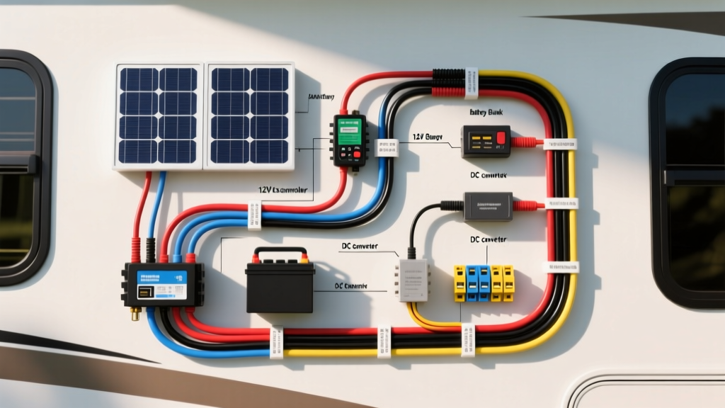
Decoding the 12V DC Architecture
Building a reliable off-grid power system requires more than just mounting panels on your roof. A properly engineered solar wiring diagram for RV applications must account for voltage drop, thermal expansion, and the unique vibration environment of a moving vehicle. Unlike residential solar, an RV's 12V DC system operates at high amperage and low voltage, meaning every connection point and wire gauge is critical to prevent resistive heating and potential fire hazards. For beginners, understanding the flow of direct current from the photovoltaic cells to the house battery bank is the first step toward achieving true energy independence on the road.
Visualizing the Solar Wiring Diagram for RV Systems
When mapping out your physical layout, think of the system in four distinct zones: Generation, Regulation, Storage, and Distribution. The physical routing of your wires must minimize distance while avoiding sharp bends or high-heat areas like exhaust components.
Component Flow and Connection Points
- Roof Generation: Solar panels are typically wired in series (to increase voltage and reduce current) using MC4 connectors. The combined positive and negative leads pass through an IP68-rated waterproof cable gland into the RV interior.
- Regulation (MPPT Controller):strong> The roof leads connect to a Maximum Power Point Tracking (MPPT) charge controller. MPPT is vastly superior to PWM for RVs because it converts excess panel voltage into usable charging amperage, especially on cloudy days or when panels are partially shaded by roof vents.
- Storage (Battery Bank):strong> The controller outputs regulated 12V/24V DC to the positive and negative busbars. Lithium Iron Phosphate (LiFePO4) batteries are the modern standard, requiring specific charging profiles configured within the MPPT controller.
- Distribution (Busbars & Inverter):strong> A heavy-duty 2/0 AWG cable runs from the main busbars to the DC-to-AC inverter, while smaller branch circuits (12 AWG to 16 AWG) feed the RV's 12V fuse panel for lights, water pumps, and ventilation fans.
Wire Gauge (AWG) Sizing and Voltage Drop
The most common mistake beginners make when executing a solar wiring diagram for RV builds is undersizing the wire. In a 12V system, even a small voltage drop translates to massive power loss and dangerous heat generation. You must size your wire based on the maximum continuous current and the one-way distance of the run, targeting a voltage drop of less than 3% for solar circuits and less than 0.5% for inverter circuits.
Furthermore, always use stranded, tinned copper wire (SAE J1128 or UL 1426 marine grade). Tinned copper resists the black oxidation that plagues bare copper in the humid, variable-temperature environment of an RV, ensuring long-term conductivity.
| Circuit Segment | Max Current | One-Way Distance | Recommended AWG | Voltage Drop Target |
|---|---|---|---|---|
| Solar Panels to MPPT | 20A (Series String) | 15 ft | 10 AWG | < 3% |
| MPPT to Positive Busbar | 40A | 5 ft | 6 AWG | < 1% |
| Busbar to Battery Bank | 100A+ | 3 ft | 2/0 AWG | < 0.5% |
| Battery to 2000W Inverter | 250A Peak | 4 ft | 2/0 AWG or 4/0 AWG | < 0.5% |
| 12V Branch (Water Pump) | 10A | 20 ft | 12 AWG | < 3% |
Overcurrent Protection: Fuses and Breakers
Every ungrounded (positive) conductor must have overcurrent protection sized to 125% of the maximum continuous load, placed as close to the power source as possible. In an RV solar diagram, this means specific fuse types for specific applications:
- Solar Array Disconnect: A DC-rated miniature circuit breaker (MCB) or a PV-rated switch between the roof gland and the MPPT controller. Never use standard AC breakers, as they lack the internal arc-chute mechanisms required to extinguish high-voltage DC arcs.
- MPPT to Busbar: An ANL or Class T fuse. For a 40A controller, use a 50A ANL fuse.
- Battery Main Fuse: A Class T fuse or Marine Battery Fuse (MRBF) mounted directly on the battery positive terminal. This protects the entire rig in the event of a catastrophic short circuit. Class T fuses offer a high Ampere Interrupting Capacity (AIC) of 20,000A, which is essential for the massive short-circuit potential of LiFePO4 batteries.
Integrating the Chassis Alternator (DC-DC Charging)
A comprehensive RV solar setup often includes a way to charge the house batteries while driving. Wiring a DC-DC charger (such as a Victron Orion or Renogy DCC50S) between the vehicle's starting battery and the RV's house battery requires careful attention to the ignition signal. The DC-DC charger must feature an 'Ignition Sense' or 'Engine Detect' wire. This small gauge wire (typically 18 AWG) is tapped into a 12V source that only powers when the engine is running (like the tow vehicle's 7-way blade connector auxiliary pin). This prevents the DC-DC charger from draining your starting battery when the engine is off, ensuring you are never stranded.
Terminal Crimping and Torque Specifications
A wiring diagram is only as good as its physical connections. Soldering is generally discouraged in high-vibration automotive and RV environments because solder wicks into the wire strands, creating a rigid point that will eventually snap under chassis flex. Instead, use high-quality adhesive-lined heat shrink terminals and a proper ratcheting crimping tool. The ratchet ensures the terminal is compressed to the exact factory specification before releasing.
When terminating heavy 2/0 AWG cables onto busbars or battery studs, torque matters. Under-torquing leads to micro-arcing and melted terminals; over-torquing strips the threads or cracks the battery post. For standard M8 (5/16') copper busbar studs, apply 5 to 6 Nm (4.4 to 5.3 lb-ft) of torque. For M10 (3/8') studs, apply 8 to 10 Nm. Always use a calibrated inch-pound torque wrench and mark the nut with a torque-seal pen for easy visual inspection during routine maintenance.
Grounding Nuances: Chassis vs. DC Negative
Beginners often confuse AC grounding, DC grounding, and chassis grounding. In a modern RV solar wiring diagram, the DC negative busbar should be the central star-ground point for all 12V loads and charging sources. While the DC negative busbar is ultimately bonded to the RV chassis in one single location (to prevent ground loops), individual solar components and inverters should run their negative wires directly back to the negative busbar, not to the nearest metal frame rail. Relying on the chassis for DC return current invites severe voltage drop and erratic sensor behavior due to paint, rust, and aluminum oxidation.
Common Troubleshooting Scenarios
If your MPPT controller shows zero solar yield despite bright sunlight, use a digital multimeter to perform a voltage drop test. Set your meter to DC Volts, place the red probe on the positive MC4 connector at the roof gland, and the black probe on the positive input terminal of the MPPT controller. Under load, if you read a voltage drop greater than 3% of your array's Vmp (Maximum Power Voltage), you have a high-resistance fault. This is almost always caused by a poorly crimped MC4 pin or a corroded inline fuse holder.
Authoritative References
For comprehensive safety standards, refer to the NFPA 1192 Standard on Recreational Vehicles, which dictates DC wiring color codes and overcurrent protection placement. Additionally, the Victron Energy Wiring Unlimited Guide provides exhaustive formulas for calculating voltage drop and battery busbar sizing. Finally, consult Blue Sea Systems Circuit Protection Guidelines for selecting the correct interrupt capacity (AIC) for your DC fuses.