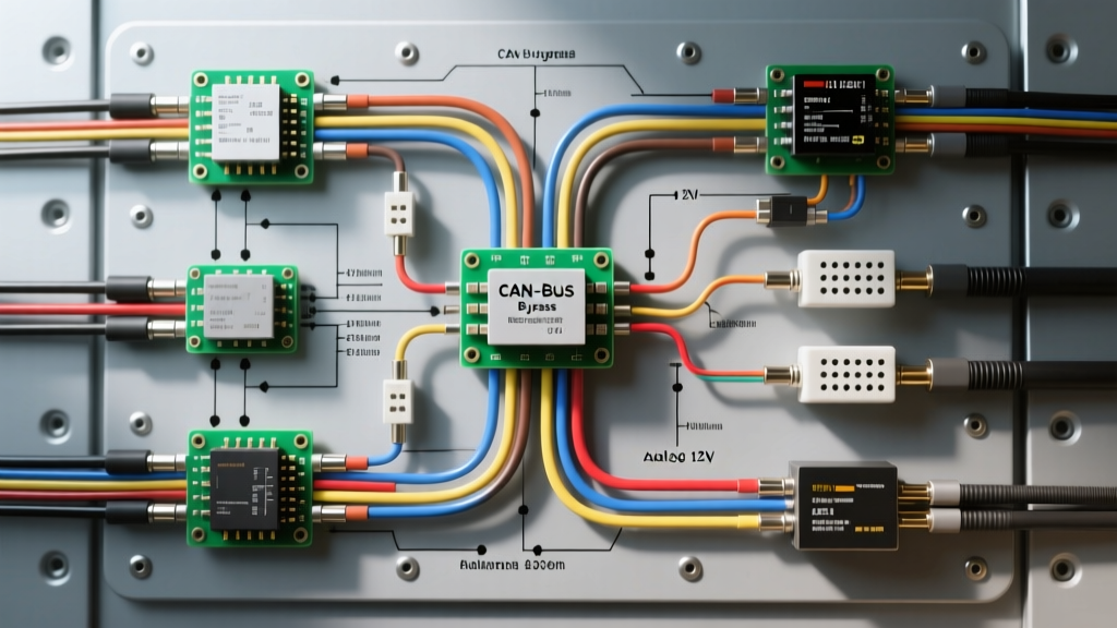
Decoding the Wiring Diagram Remote Start Architecture
Interpreting a wiring diagram remote start schematic requires a fundamental understanding of both legacy analog 12V circuits and modern multiplexed data networks. Unlike simple accessory installations, remote start systems must seamlessly interface with the vehicle's immobilizer, body control module (BCM), and powertrain control module (PCM). A failure to correctly map the ignition sequence or bypass the transponder ring will result in a crank-no-start condition or trigger the factory anti-theft siren. According to the Mobile Electronics Certified Professional (MECP) standards, technicians must verify wire polarity and voltage drop using a digital multimeter (DMM) rather than relying solely on test lights, which can draw excessive current and damage sensitive solid-state BCM outputs.
Industry-Standard RF Module Analog Pinouts
While specific manufacturer diagrams (such as Compustar, Viper, or Prestige) vary slightly, the core 24-pin and 12-pin analog harnesses follow a widely accepted industry color code. When reading the primary ignition and starter wiring diagram, the following specifications apply to the heavy-gauge and light-gauge outputs. These outputs typically utilize internal 30A or 40A relays, necessitating precise wire gauge selection to prevent thermal degradation.
| Wire Color | Function | AWG Rating | Circuit Specifications & Notes |
|---|---|---|---|
| Red (Heavy) | +12V Battery Constant | 10 AWG | Must be fused within 18 inches of the battery. Powers main RF module and internal relays. |
| Black (Heavy) | Chassis Ground | 10 AWG | Must connect to bare, unpainted OEM chassis metal. Do NOT use factory grounding studs shared with high-draw accessories. |
| Yellow | Ignition 1 (IGN1) | 12 AWG | Primary ignition circuit. Shows +12V in ON and START positions. |
| Green | Ignition 2 (IGN2) | 14 AWG | Secondary ignition. Often drops out during the START crank phase on older vehicles, but remains active on modern push-to-start models. |
| Blue | Starter Output | 12 AWG | Outputs +12V only during the crank sequence. Must be connected to the starter side of the factory immobilizer/starter interrupt relay. |
| Purple | Accessory (ACC) | 14 AWG | Powers HVAC and radio circuits. Active in ON position, drops during START. |
| Orange | Brake Light Input | 18 AWG | Connected to the brake switch (+12V trigger). Acts as a primary safety shutdown for the remote starter. |
| Pink / White | Hood Pin Switch | 18 AWG | Ground-triggered (-). Shuts down the system if the hood is open to prevent mechanic injuries. |
CAN-Bus Data Integration vs. Analog Hardwiring
Modern vehicles utilize Controller Area Network (CAN) and Local Interconnect Network (LIN) buses to transmit multiplexed data. Relying solely on analog hardwiring for door locks, tachometer signals, and immobilizer bypasses is obsolete and often impossible on vehicles with encrypted data lines. A modern wiring diagram remote start setup relies heavily on a data bypass module (such as the Fortin EVO-ALL or iDatalink ADS-MAX). These modules translate the RF kit's analog commands into digital CAN-bus messages.
OBD2 Port Flashing & Data Pinouts
Before installing the hardware, bypass modules must be flashed with vehicle-specific firmware via the OBD2 port. The Fortin Auto Radio Installation Guides emphasize that a stable +12V source and pristine CAN-bus connections are mandatory during the flashing process to prevent module bricking. The standard SAE J1962 OBD2 diagnostic connector pinout used for data retrieval is as follows:
- Pin 6 (CAN High): Typically Green/White or Yellow. Carries the dominant/high-side CAN signal.
- Pin 14 (CAN Low): Typically Green/Black or Green. Carries the recessive/low-side CAN signal.
- Pin 16 (Battery +): +12V Constant power.
- Pins 4 & 5 (Ground): Chassis and Signal ground references.
When hardwiring the CAN-bus connection directly to the BCM or PCM (bypassing the OBD2 port for a stealth installation), technicians must measure the termination resistance. A healthy CAN-bus network will read exactly 60 ohms across CAN-H and CAN-L when the vehicle is asleep and the battery is connected. A reading of 120 ohms indicates a missing termination resistor, while 0 ohms indicates a short circuit.
Immobilizer Bypass & Starter Interrupt Relay Wiring
To prevent vehicle theft, remote start systems incorporate a starter interrupt (kill) relay. This ensures the vehicle cannot be stolen via a forced ignition cylinder turn while the remote start system is armed. The industry standard utilizes a 5-pin Bosch-style SPDT (Single Pole Double Throw) relay. Understanding the relay pinout is critical when reading the interrupt section of the wiring diagram:
| Relay Pin | Internal Connection | Remote Start Wiring Application |
|---|---|---|
| 86 | Coil (+) | Connected to +12V Constant or switched ignition (depending on fail-safe preference). |
| 85 | Coil (-) | Connected to the RF module's Starter Kill Output (Ground trigger when armed). |
| 30 | Common (C) | Connected to the vehicle's Starter Solenoid wire (coming from the ignition switch). |
| 87a | Normally Closed (NC) | Connected to the vehicle's Starter Solenoid wire (going to the starter motor). |
| 87 | Normally Open (NO) | Not used in a standard starter interrupt configuration (leave taped/insulated). |
In this configuration, when the vehicle is armed, the RF module grounds Pin 85, energizing the coil. This breaks the connection between 30 and 87a, physically preventing the starter from engaging via the key. When the remote start is triggered, the module releases the ground on Pin 85, restoring the starter circuit and allowing the RF module's internal starter relay to crank the engine.
Advanced Troubleshooting: Signal Loss & Voltage Drop
Even with a perfect wiring diagram remote start reference, real-world installations encounter environmental and electrical variables. Below are advanced diagnostic procedures for common failure modes:
1. Crank-No-Start (Immobilizer Desync)
If the engine cranks via remote start but immediately dies after 2-3 seconds, the immobilizer bypass is failing. This is rarely a wiring fault and usually a firmware or key-learning issue. For push-to-start vehicles using an iDatalink module, ensure the physical OEM key fob battery is not depleted, as some bypass modules rely on the fob's RFID signal amplifying through the transponder ring. Consult iDatalink Maestro Technical Support for the specific 10-second ignition cycling reset procedure required to re-sync the bypass module with the vehicle's PCM.
2. Premature Crank Termination
Remote starters rely on a tachometer signal or CAN-bus RPM data to know when the engine has caught, prompting the module to release the starter relay. If the analog tachometer wire (usually Green/White) is connected to an incorrect injector coil or ignition coil, the module will read erratic AC voltage and terminate the crank sequence prematurely to prevent starter gear damage. Always verify the tachometer signal using a DMM set to AC Voltage; a valid tach signal typically reads between 1.0V and 4.0V AC at idle.
3. CAN-Bus Wakeup Failures
On vehicles with aggressive sleep modes (e.g., modern Chrysler/Lexus platforms), the CAN-bus goes completely dormant. If the bypass module does not send the correct digital "wake-up" frame before attempting to send the remote start command, the BCM will ignore the request. Ensure the CAN-H and CAN-L wires are spliced using military-spec solder sleeves or high-quality Posi-Tap connectors. Standard Scotch-Loks will pierce the wire insulation too deeply, altering the twisted-pair geometry, introducing electromagnetic interference (EMI), and causing intermittent data packet loss.
By treating the wiring diagram not just as a map, but as a technical specification document detailing AWG limits, data protocols, and relay logic, installers can achieve OEM-level reliability in aftermarket remote start integrations.