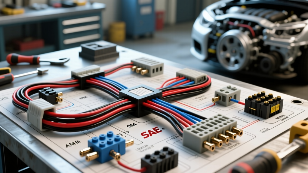
Introduction to Automotive Schematic Standards
Learning how to read a car wiring diagram is the fundamental skill separating a parts-swapper from a true automotive electrical diagnostician. Modern vehicles contain over 5,000 individual circuits, managed by dozens of interconnected modules. To navigate this complexity, technicians must rely on standardized schematic diagrams governed by organizations like SAE International and the ISO 6722 standard for road vehicle cables. This technical reference guide breaks down the exact symbols, wire color codes, AWG specifications, and connector pinout logic required to accurately trace and diagnose vehicle electrical systems.
Decoding Standard Wiring Diagram Symbols
OEM wiring diagrams use a specific lexicon of symbols to represent physical components and logical connections. Unlike residential electrical diagrams, automotive schematics heavily utilize alphanumeric identifiers to pinpoint physical locations on the chassis.
| Symbol / Code | Component Name | Function & Real-World Application |
|---|---|---|
| GND / Chassis Ground | Chassis Ground | Physical connection to the vehicle body or engine block. Usually secured with an M6 or M8 bolt torqued to 10-15 Nm. Poor ground G102 is a common cause of sensor voltage drops. |
| SGND / Signal Ground | Signal Ground | Low-current ground reference routed back to the ECU. Used for sensitive 5V reference sensors (e.g., MAP, TP) to prevent electromagnetic interference (EMI). |
| S-Prefix (e.g., S104) | Wire Splice | Indicates a physical soldered or ultrasonic weld splice in the harness. S100-S199 typically denote engine bay splices, while S200-S299 indicate dashboard harness splices. |
| C-Prefix (e.g., C205) | Inline Connector | Represents a separable inline harness connector. Crucial for isolating faults between the cabin and engine bay bulkheads. |
| Normally Open (NO) | Relay Contact | Contacts that close only when the relay coil is energized by the PCM. Commonly used for fuel pump and cooling fan primary circuits. |
Ground Voltage Drop Testing: According to SAE standards, a standard chassis ground should exhibit no more than a 0.10V (100mV) drop under load. Sensor grounds should read less than 0.05V (50mV). If your diagram shows a sensor sharing a ground node with a high-current load like a cooling fan, a corroded G-node will cause the fan's return current to back-feed into the sensor ground, skewing the 5V reference signal.
Understanding OEM Wire Color Codes and Tracer Stripes
When figuring out how to read a car wiring diagram, color code interpretation is critical. Automotive wire insulation utilizes a base color with a secondary tracer stripe. The base color constitutes roughly 80-85% of the wire surface, while the tracer accounts for the remaining 15-20%.
- General Motors (GM): Uses abbreviations like DK GRN (Dark Green) or LT BLU (Light Blue). A wire labeled RD/WHT is Red with a White tracer.
- Ford: Often uses a dual-letter code system, such as OG/BK (Orange with Black tracer) or VT/LG (Violet with Light Green).
- Chrysler/Stellantis: Employs a two-letter code, e.g., DG/OR (Dark Green with Orange tracer).
- European (DIN 72551): German manufacturers (BMW, VW, Audi) typically use solid colors with numerical suffixes or rely heavily on metric cross-sectional area printing directly on the insulation.
Expert Tip: Never rely solely on color for circuit identification. UV exposure, heat, and oil contamination can fade a Light Blue (LT BLU) wire to look exactly like a White (WHT) or Gray (GRY) wire. Always verify the circuit using a digital multimeter (DMM) and the schematic's origin/destination points.
Wire Gauge (AWG) vs. Cross-Sectional Area (mm²) Specifications
Automotive wiring diagrams specify conductor thickness to ensure the wire can handle the circuit's amperage without excessive voltage drop or thermal melting. North American diagrams use American Wire Gauge (AWG), while European and Asian diagrams use metric cross-sectional area (mm²).
| AWG Size | Metric (mm²) | Max Continuous Amps | Typical Automotive Circuit Application |
|---|---|---|---|
| 22 AWG | 0.35 mm² | 3 - 5 Amps | CAN Bus twisted pairs, low-current sensor signals, LIN bus communication. |
| 18 AWG | 0.80 mm² | 8 - 10 Amps | 5V Reference circuits, oxygen sensor heaters, injector pulse signals. |
| 14 AWG | 2.00 mm² | 15 - 18 Amps | Headlight low beams, interior lighting, power window switch logic. |
| 10 AWG | 5.00 mm² | 25 - 30 Amps | Headlight high beams, ABS pump motor feeds, ignition coil primary feeds. |
| 4 AWG | 20.00 mm² | 80 - 100 Amps | Alternator B+ output to battery, starter motor solenoid feeds. |
When repairing a harness, always match or exceed the OEM cross-sectional area. Splicing a 20 AWG wire into a damaged 14 AWG headlight circuit will create a high-resistance bottleneck, leading to localized heating and eventual wire insulation melt-down.
Power Distribution, Fuses, and Relay Logic
Wiring diagrams map the flow of current from the battery through the power distribution center (PDC) to the loads. Understanding fuse types and relay logic is critical. Most modern vehicles use ATO (Standard Blade), Mini, and Low-Profile Mini fuses, governed by ISO 8820 standards. When reading the diagram, trace the B+ (Battery Positive) feed through the fuse block. Note that OEM diagrams often label constant battery power as "B+" or "HOT AT ALL TIMES," while ignition-switched power is labeled "IGN" or "RUN/START."
Relay logic is depicted using standard coil and switch symbols. A common failure mode occurs when the PCM provides the ground path for a relay coil, but the internal driver transistor fails open. The diagram will show the coil receiving B+ from a fused ignition feed, while the PCM pin provides the ground. If you measure 12V at the relay control pin with the circuit commanded "ON," the PCM driver has failed internally, as it should pull the voltage near 0V to energize the coil.
Navigating ECU/PCM Pinouts and Connector Cavities
The most common mistake technicians make when learning how to read a car wiring diagram is misinterpreting connector views. Diagrams universally depict connectors from the Wire Side (the back of the connector where the wires enter), not the Mating Side (the face that plugs into the component). This ensures that cavity numbers align logically with the technician's perspective while probing the harness.
Terminal Locking Mechanisms: TPA and CPA
Modern connectors, such as the Aptiv (formerly Delphi) Metri-Pack 2.8 or Molex MX150 series, utilize two-stage locking systems:
- Primary Lock: The internal metal tang on the terminal itself that snaps into the plastic housing cavity.
- TPA (Terminal Position Assurance): A secondary plastic comb or wedge inserted after terminals are seated. If a terminal is not fully seated, the TPA will physically block insertion, preventing "pushed-back" pins that cause intermittent open circuits.
- CPA (Connector Position Assurance): An external lock (often red or yellow) that prevents the male and female connector halves from vibrating apart under heavy engine harmonics.
Real-World Troubleshooting: Tracing a CAN Bus Circuit
Let us apply these principles to a high-speed Controller Area Network (CAN) bus diagnosis. When viewing the schematic for a CAN bus network, you will identify two primary wires: CAN High (CAN H) and CAN Low (CAN L). These are routed as a Shielded Twisted Pair (STP) to reject EMI from the ignition system and alternator.
According to ISO 11898-2 standards, a healthy high-speed CAN bus requires two 120-ohm termination resistors placed at the physical ends of the network bus, usually inside the ECU and the instrument cluster. When you read the wiring diagram and locate these modules, you can perform a network integrity test:
- Disconnect the vehicle battery to prevent back-feeding voltage into the DMM.
- Locate the Data Link Connector (DLC) OBD-II port. The diagram will show Pin 6 as CAN H and Pin 14 as CAN L.
- Measure resistance across DLC Pin 6 and Pin 14. You should read exactly 60 ohms (two 120-ohm resistors in parallel).
- If the diagram indicates three termination resistors (some heavy-duty trucks use a third in the TCM), the math shifts. Always verify the specific OEM topology in the service manual.
- If you read 120 ohms, the diagram helps you trace the bus line to find which end-node is missing or has an open circuit in its connector cavity.
During active communication, CAN H oscillates between 2.5V (recessive) and 3.5V (dominant), while CAN L oscillates between 2.5V (recessive) and 1.5V (dominant). The diagram will note if the network utilizes a fault-tolerant architecture (ISO 11898-3), which allows communication to continue on a single wire if the other is severed, though at a reduced baud rate.
Summary and Best Practices
Mastering how to read a car wiring diagram requires treating the schematic as a precise engineering map rather than a simple illustration. Always verify connector cavity views, respect AWG-to-metric conversions during repairs, and utilize the alphanumeric splice and ground codes to physically locate faults on the chassis. For further reading on automotive electrical standards, consult the Bosch Automotive Electrics manuals and SAE technical papers.