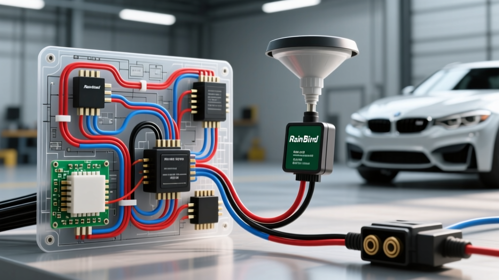
The Irrigation vs. Automotive Sensor Confusion
If you are currently searching for a Rain Bird rain sensor wiring diagram to retrofit automatic wipers onto your car, truck, or SUV, stop immediately and step away from the wire strippers. Rain Bird is a premier manufacturer of agricultural and residential irrigation systems, not automotive electronics. Their rain sensors (such as the WR2 or RSDBEX) are designed to interrupt 24VAC sprinkler solenoid circuits when precipitation is detected.
Every year, automotive electrical shops see vehicles towed in with catastrophic Body Control Module (BCM) failures. The root cause? DIYers attempting to splice an irrigation rain sensor into a modern vehicle’s multiplexed wiper stalk circuit. Modern automotive automatic wiper systems do not use simple mechanical relays or conductive grid pads; they rely on complex optical refraction sensors communicating over a 12V LIN (Local Interconnect Network) bus. Misinterpreting an irrigation diagram for an automotive application is a fast track to frying an $800+ BCM.
The 24VAC vs. 12V LIN-Bus Catastrophe
The most dangerous mistake occurs when a builder attempts to use a Rain Bird sensor’s 'Normally Closed' (NC) relay contacts to interrupt the 12VDC power feed to the windshield wiper motor. This fundamentally misunderstands how modern vehicle wiper systems operate.
How Automotive Rain Sensors Actually Work
OEM automotive rain sensors (manufactured by Bosch, TRW, or Valeo) are mounted behind the rearview mirror against the windshield glass. They utilize an infrared LED that projects light into the glass at a specific angle. When the glass is dry, the light reflects back into a photodiode. When raindrops hit the glass, the optical refraction index changes, scattering the light. The sensor’s internal microcontroller calculates the scatter rate and sends a digital PWM (Pulse Width Modulation) signal over a single-wire LIN bus to the BCM, which then commands the wiper motor speed.
The Fatal Splice
If you wire a 24VAC Rain Bird transformer and relay into a vehicle's wiper circuit, you risk introducing alternating current into a sensitive direct-current CAN/LIN network. Even if you attempt to use the Rain Bird sensor to trigger a standard 12VDC Bosch-style automotive relay to emulate a wiper stalk signal, the BCM will immediately detect an abnormal voltage drop or missing LIN-bus handshake. This will trigger a hard fault code (such as U1512: Lost Communication With Rain Sensor) and permanently disable the automatic wiper function until the codes are cleared with a bidirectional OBD2 scanner.
Correct Automotive Rain Sensor Pinouts (Bosch/TRW)
When performing an OEM-plus retrofit or diagnosing a failing automatic wiper system, you must reference automotive-specific pinouts, not irrigation manuals. Below is the standard 3-pin configuration used on most GM, Ford, and Chrysler vehicles equipped with Bosch or TRW optical sensors.
| Pin / Function | Automotive OEM (12V LIN Sensor) | Rain Bird WR2 (Irrigation - DO NOT USE) |
|---|---|---|
| Pin 1: Power | 12VDC Ignition Switched (Red/White wire, 18 AWG) | 24VAC Common (Yellow wire) |
| Pin 2: Ground | Chassis Ground (Black wire, 18 AWG) | 24VAC Normally Closed (Red wire) |
| Pin 3: Data | LIN Bus Data (Yellow/Green wire, 20 AWG) | 24VAC Normally Open (Blue wire) |
Note: Always use SAE J1128 TXL or GXL primary wire for automotive harnesses. Standard THHN or irrigation wire lacks the chemical and heat resistance required for under-hood or windshield cowl environments.
Top 3 Fatal Wiring Mistakes & Safety Warnings
1. Grounding to the Windshield Cowl or Mirror Mount
The Mistake: Using the metal bracket of the rearview mirror or the sheet metal of the windshield cowl as the ground return for the sensor.
The Reality: Modern vehicles use isolated grounds to prevent electromagnetic interference (EMI) on sensitive data buses. A poor ground will cause the LIN bus voltage to float, resulting in phantom wiper activations or complete module lockouts.
The Fix: Run a dedicated 18 AWG ground wire directly to a verified, paint-free chassis ground point or the interior A-pillar ground bus bar. Use a ring terminal with a star washer to ensure metal-to-metal contact.
2. Reusing the Optical Coupling Pad
The Mistake: Installing a salvaged or aftermarket rain sensor without replacing the silicone optical coupling gel pad.
The Reality: The sensor relies on a specific refractive index bridge between the plastic housing and the glass. If there is an air gap, the infrared light will scatter internally, tricking the sensor into thinking it is pouring rain. The wipers will run continuously on high speed, burning out the wiper motor park switch.
The Fix: Always use a new OEM-spec silicone RTV optical pad. Clean the interior glass with isopropyl alcohol (not ammonia-based glass cleaners, which leave a conductive film that causes static interference).
3. Splicing into Constant 12V (Parasitic Draw)
The Mistake: Wiring the sensor’s Pin 1 (Power) to a constant 12V battery source so it 'remembers' the rain settings.
The Reality: Automotive rain sensors do not have non-volatile memory for wiper states; that is handled by the BCM. Feeding constant 12V to the sensor keeps the internal microcontroller and IR emitter awake, drawing 40-80mA continuously. Over a week, this will drain your vehicle's battery below the threshold required to crank the starter.
The Fix: Pin 1 must be wired to an Ignition/Run (IGN) fused circuit, or directly to a BCM-switched accessory output.
Proper 12V Wiper Retrofit Architecture
If you are retrofitting automatic wipers onto an older classic car or a base-model truck that did not come with a LIN-bus BCM, do not use irrigation parts. Instead, use a standalone 12VDC optical rain sensor kit paired with a dedicated wiper delay relay module (such as those offered by Ron Francis Wiring or Painless Performance).
- Sensor Placement: Mount the optical sensor in the upper sweep zone of the driver-side wiper, avoiding the black ceramic frit band (the black dots around the edge of the glass), which blocks infrared light.
- Relay Integration: Use a heavy-duty 40A automotive relay to handle the wiper motor's inrush current. The optical sensor's low-amperage 12VDC trigger wire should connect to Pin 85 of the relay, while Pin 86 goes to ground.
- Connector Selection: Never use wire nuts or standard heat-shrink butt splices in the windshield cowl. Use TE Connectivity AMP Superseal 1.5 or Deutsch DT connectors to ensure a waterproof, vibration-resistant seal against high-pressure car washes and engine bay heat.
Diagnostic Troubleshooting Tree
If your OEM automatic wipers have ceased functioning, follow this diagnostic path before replacing parts:
- Symptom: Wipers work manually via the stalk, but 'AUTO' mode does nothing.
- Test: Check for 12V at Pin 1 (IGN) and continuity to ground at Pin 2.
- Fix: If power and ground are good, the issue is on the LIN bus or the sensor itself.
- Symptom: Wipers activate immediately on 'AUTO' even when the glass is bone dry.
- Test: Inspect the optical silicone pad for air bubbles, dirt, or degradation.
- Fix: Clean glass, apply new optical pad, and press sensor firmly against the glass to expel trapped air.
- Symptom: U1512 Code stored in BCM.
- Test: Use an oscilloscope on Pin 3 (Data). You should see a 12V square-wave PWM signal. A flat 12V line indicates a short to power; a flat 0V line indicates a short to ground.
- Fix: Repair the 20 AWG LIN bus wire between the sensor and the BCM. For deeper network diagnostics, refer to Haynes automotive electrical tutorials on multiplexed networks.
By understanding the vast electrical differences between landscape irrigation and modern automotive networks, you can avoid costly mistakes. Leave the Rain Bird rain sensor wiring diagrams for the sprinkler system, and stick to OEM-specific LIN-bus schematics for your vehicle's electrical integrity.