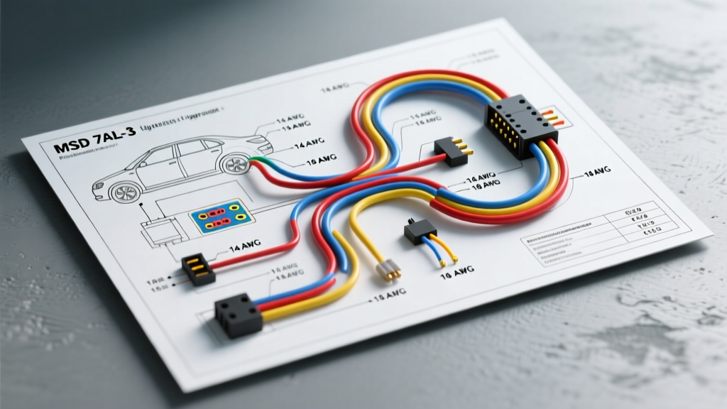
Executing the MSD 7AL-3 Ignition Upgrade Project
When transitioning from a standard HEI, points-type, or entry-level CDI system to a professional racing setup, referencing an accurate wiring diagram for MSD 7AL-3 controllers (Part Number 7220) is the most critical step in your build. The 7AL-3 is a high-output capacitive discharge (CD) ignition system designed for extreme RPM environments, featuring a built-in 3-step rev limiter, data acquisition compatibility, and multi-spark technology below 3,000 RPM. Unlike basic street upgrades, integrating this unit requires strict adherence to heavy-gauge power delivery, precise trigger signal routing, and proper coil pairing.
This guide provides the definitive wiring schematic, wire color code chart, and installation best practices for your 7AL-3 modification project. Whether you are wiring a dedicated drag car with a flying magnet crank trigger or a circle track car utilizing a magnetic pickup distributor, the electrical architecture outlined below ensures maximum spark energy and noise rejection.
Core Power and Ground Architecture
The most common failure point in high-end ignition upgrades is voltage drop under load. The 7AL-3 capacitor bank requires massive, instantaneous current to recharge between sparks at high RPM. Relying on factory chassis wiring or undersized relays will result in misfires and blown internal components.
Main Battery and Ground Leads
- Heavy Red Wire (Main 12V+): This 8 AWG wire must be connected directly to the positive terminal of the battery or a dedicated 120A continuous-duty remote solenoid. Do not route this through the ignition switch. Use a master cutoff switch and a dedicated ignition relay triggered by the key switch.
- Heavy Black Wire (Main Ground): This 8 AWG wire must be grounded directly to the engine block or the negative battery terminal. If grounding to the block, use a dedicated brass or copper grounding lug, sand the mounting surface down to bare metal, and secure it with a grade 8 bolt. Avoid grounding to aluminum cylinder heads or painted brackets.
- Wire Extension Rules: If you must extend the heavy Red or Black wires to reach a trunk-mounted battery, upgrade to SAE J1128 compliant 4 AWG or 2 AWG fine-strand welding cable. Solder all splices and seal them with adhesive-lined heat shrink to prevent corrosion and high-resistance joints.
MSD 7AL-3 Wire Color Code & Function Chart
Use the following reference table when terminating your harness. Always use open-barrel crimp connectors for high-vibration race environments, as solder-only joints are prone to fatigue fracturing under harmonic engine vibration.
| Wire Color | Function | AWG Size | Destination / Termination Notes |
|---|---|---|---|
| Heavy Red | Main 12V+ Power | 8 AWG | Battery (+) via 120A Relay / Cutoff Switch |
| Heavy Black | Main Ground | 8 AWG | Engine Block or Battery (-) |
| Orange | Coil Positive (+) | 14 AWG | Ignition Coil (+) Terminal |
| Orange/Black | Coil Negative (-) | 14 AWG | Ignition Coil (-) Terminal |
| Purple | Magnetic Pickup (+) | 18 AWG | Distributor / Crank Trigger Pickup (+) |
| Purple/White | Magnetic Pickup (-) | 18 AWG | Distributor / Crank Trigger Pickup (-) |
| White | Points / Amplifier Trigger | 18 AWG | Points or External Igniter Output (Magnetic Unused) |
| Yellow | Starter Bypass | 14 AWG | Starter Solenoid 'I' Terminal (Bypasses Ballast) |
| Gray | Tachometer Output | 18 AWG | Tach Signal In (12V Square Wave) |
| Blue | Retard / Activator | 18 AWG | Transbrake / Momentary Switch for Retard |
Trigger Signal Wiring: Magnetic Pickup vs. Points
The 7AL-3 offers multiple trigger inputs, but only one should be active at a time. Selecting the wrong trigger wiring will result in a no-spark condition or erratic timing curves.
Magnetic Pickup (Crank Trigger or Distributor)
For 95% of racing applications, a magnetic pickup is utilized. Connect the Purple wire to the positive pickup lead and the Purple/White wire to the negative lead. Crucial Modification Note: If using a flying magnet crank trigger (e.g., MSD PN 8610), ensure the air gap between the sensor and the magnets is set precisely between 0.040" and 0.080". Route the pickup wires away from exhaust headers and alternator outputs to prevent Electromagnetic Interference (EMI). If extending the pickup wires, use twisted-pair, shielded cable and ground the shield at the MSD unit only.
Points or Amplifier Trigger
If triggering the 7AL-3 via factory breaker points or an external igniter module, connect the White wire to the points or the negative side of the ignition coil. The Purple and Purple/White wires must be capped and isolated. Never leave unused trigger wires dangling near moving engine components.
Ignition Coil and Starter Bypass Configuration
Coil Selection and Wiring
Capacitive discharge ignitions require specific low-resistance coils. Wire the Orange wire to the Coil (+) and the Orange/Black wire to the Coil (-). Specification Requirement: Use an MSD Blaster series coil or equivalent. The primary resistance must be between 0.5 and 0.9 ohms, and secondary resistance between 4,000 and 6,000 ohms. Using a standard OEM coil with an internal ballast resistor will choke the CD output and destroy the 7AL-3's internal IGBT switches.
Yellow Wire: Starter Bypass
During cranking, voltage to the ignition switch can drop below 9V. The Yellow wire connects to the 'I' (Ignition) terminal on the starter solenoid. This provides a direct 12V+ feed to the MSD unit only while the starter is engaged, ensuring maximum cranking spark. If your vehicle uses a modern gear-reduction starter without an 'I' terminal, you must wire a dedicated bypass relay.
Configuring the 3-Step Rev Limiter and Tach Output
The 7AL-3 features a 3-step rev limiter module, essential for drag racing staging and circle track pit speed limiting. The module plugs into the dedicated port on the side of the unit.
- Step 1 (Transbrake / Burnout): Activated when 12V is applied to the White/Blue wire on the 3-step harness. Typically wired in parallel with the transbrake solenoid button.
- Step 2 (Staging / 2-Step): Activated when 12V is applied to the White/Orange wire. Used for building boost on the starting line.
- Step 3 (Overrev / Top End): Always active as a safety net. Set this chip 200-300 RPM above your maximum shift point to prevent engine destruction on missed shifts.
Tachometer Output (Gray Wire): The Gray wire outputs a 12V square wave signal (1 pulse per cylinder firing). Most modern aftermarket tachometers (AutoMeter, Stack) accept this directly. If using an OEM tachometer, you will likely need an MSD Tach Adapter (PN 8910) to step down the voltage and match the OEM pulse width.
Symptom-Cause-Fix Troubleshooting Tree
When diagnosing a no-spark condition post-installation, follow this expert decision tree before replacing components:
- Symptom: Engine cranks but has zero spark.
- Check 1: Measure voltage at the Heavy Red wire during cranking. If below 10V, check the main relay and Yellow bypass wire.
- Check 2: Verify coil primary resistance. If > 1.5 ohms, replace the coil.
- Symptom: Engine backfires through the carburetor at high RPM.
- Check 1: Inspect magnetic pickup air gap. A gap > 0.100" causes signal dropout at high RPM, resulting in late spark.
- Check 2: Check for EMI interference. Ensure pickup wires are not zip-tied to spark plug wires or exhaust headers.
- Symptom: Tachometer reads erratically or pegs to max RPM.
- Fix: The Gray tach wire is likely shorting to ground, or the tachometer requires an adapter. Install an MSD PN 8910 filter.
Authoritative References & Further Reading
For complete technical specifications, software mapping (via Pro-Data+), and warranty information, always consult the manufacturer's engineering documentation and established automotive electrical standards: