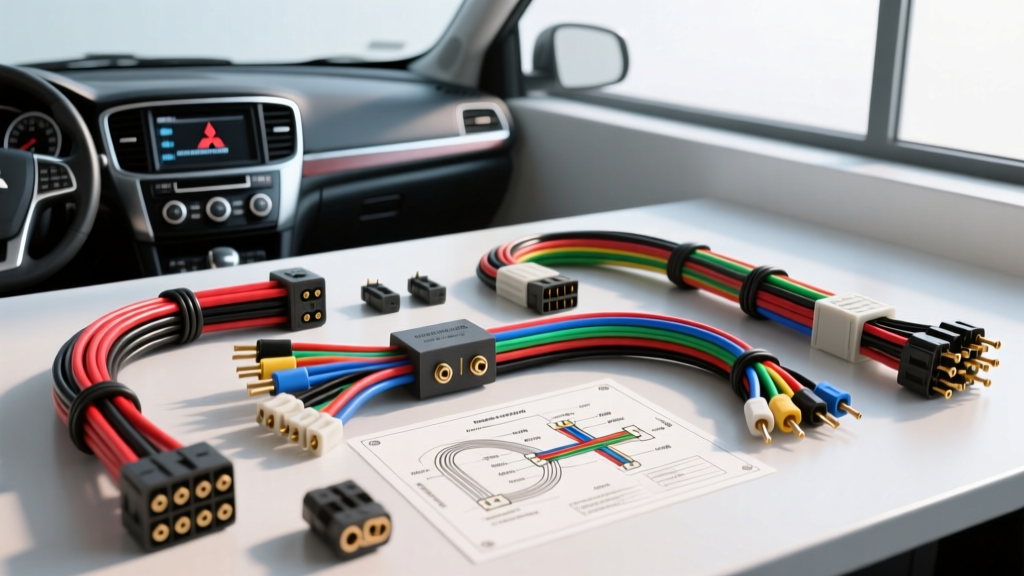
The Reality of Mitsubishi Stereo Wiring Diagram PDFs
When DIYers and mobile electronics installers search for a color code factory wiring mitsubishi stereo wiring diagram pdf, they are usually looking for a quick shortcut to bypass the dealer service manual. While a PDF schematic provides the raw pinout data, it rarely accounts for the real-world variables of modern automotive electrical systems: CAN-bus sleep states, Rockford Fosgate amplifier integration, and the specific tooling required to make reliable, low-resistance connections. This guide breaks down the actual cost and tool requirements for executing a professional-grade stereo installation in Mitsubishi vehicles (focusing on the widely used 2008-2017 Lancer, Outlander, and Eclipse platforms), contrasting the 'hardwire' method against commercial harness adapters.
Cost Analysis: Harness Adapters vs. Hardwiring
Interpreting a factory Mitsubishi wiring diagram is only the first step. The primary financial decision is whether to purchase a plug-and-play T-harness or to manually splice into the OEM wiring using primary automotive cable. Below is a cost and effort matrix for a standard double-DIN receiver upgrade.
| Component / Task | Hardwire Method (Cost) | Adapter Harness Method (Cost) | Time & Risk Factor |
|---|---|---|---|
| Main Power & Speaker Harness | $8.00 (18/20 AWG wire, tape) | $24.99 (e.g., Metra 70-7301) | Hardwire adds 45 mins; higher risk of short circuits. |
| Steering Wheel Control (SWC) | $12.00 (Resistor ladder kit) | $79.99 (Axxess ASWC-1 or PAC) | Resistors require precise soldering; adapters auto-detect. |
| Rockford Fosgate Amp Bypass | $15.00 (16 AWG speaker wire) | $45.00 (Metra LC4 Line Converter) | Running new wire through door boots is labor-intensive. |
| CAN-Bus Data Retention | $0 (Requires advanced DMM testing) | $110.00 (PAC RP7-MI Interface) | Hardwiring CAN-bus risks ECU parasitic drain. |
Expert Verdict: For vehicles equipped with the factory Rockford Fosgate premium audio system and CAN-bus data networks (2012+ models), the adapter method is highly recommended. The $150+ premium in parts saves hours of labor and prevents costly electrical faults.
Essential Tool Requirements & Budget
If you opt to use the factory PDF diagrams to hardwire or verify adapter harnesses, you must adhere to strict automotive wiring standards. According to the SAE J1128 Low-Tension Primary Cable Standard, automotive wire must withstand high temperatures and chemical exposure. Standard household THHN wire is unacceptable.
1. Wire Strippers & Crimpers (Budget: $45 - $85)
Mitsubishi typically uses 0.5mm² (approx. 20 AWG) for audio signals and 0.85mm² (18 AWG) for power, ground, and illumination circuits. You need precision micro-strippers that will not nick the copper strands. Nicking 20 AWG wire reduces its current-carrying capacity and creates a hotspot. Use a ratcheting crimper for heat-shrink butt connectors to ensure a watertight, vibration-proof seal.
2. Digital Multimeter (DMM) (Budget: $60 - $250)
A reliable DMM is non-negotiable for verifying the OEM wiring diagram against the actual vehicle. Factory PDFs are notorious for mid-year production changes. You must verify the constant 12V (Battery) and switched 12V (ACC) lines, as well as test the CAN-H and CAN-L voltages before tapping into them.
3. Trim Removal & Panel Tools (Budget: $20)
Mitsubishi dash panels are secured with fragile nylon push-clips and hidden 10mm bolts (usually located behind the climate control ashtray or inside the glovebox). Nylon pry tools prevent marring the soft-touch plastics.
Decoding the Factory Color Codes: Lancer & Outlander Pinouts
Below is a reference table derived from standard Mitsubishi 14-pin and 20-pin OEM connectors. Always verify with a DMM, as Metra Electronics and OEM service manuals note that wire colors can vary slightly between Japanese Domestic Market (JDM) and USDM imports.
| Pin | Function | OEM Wire Color (Typical USDM) | AWG / Spec |
|---|---|---|---|
| 1 | +12V Constant (Battery) | Red / Yellow Stripe | 18 AWG |
| 2 | +12V Switched (ACC) | Blue / Red Stripe | 18 AWG |
| 3 | Ground (Chassis) | Black | 18 AWG |
| 4 | Illumination (Dimmer) | Green / White Stripe | 20 AWG |
| 5 | Power Antenna / Amp Turn-On | Blue / White Stripe | 20 AWG |
| 11 | CAN-H (Data Bus High) | White / Red Stripe | 20 AWG (Twisted Pair) |
| 12 | CAN-L (Data Bus Low) | White / Black Stripe | 20 AWG (Twisted Pair) |
Speaker Wire Color Matrix (Standard 8-Speaker System)
- Front Left (+/-): White / White-Black
- Front Right (+/-): Gray / Gray-Black
- Rear Left (+/-): Green / Green-Black
- Rear Right (+/-): Purple / Purple-Black
Note: If the vehicle has the Rockford Fosgate system, these speaker wires at the head unit are low-level pre-out signals feeding the factory DSP/Amplifier in the trunk or under the seat. Splicing standard 4-ohm aftermarket speakers directly into these wires will result in severe distortion and potential damage to the head unit's pre-amp stage.
CAN-Bus Integration & Parasitic Draw Troubleshooting
Modern Mitsubishis utilize a CAN-bus network to manage accessory power and steering wheel controls. If you are using a data retention interface like the PAC RP7-MI Radio Replacement Interface, you must splice into the CAN-H and CAN-L twisted pair.
The CAN-Bus Sleep State Issue
A common failure mode when hardwiring CAN-bus lines is introducing a parasitic battery drain. The vehicle's ECU and ETACS (Electronic Time and Alarm Control System) must 'go to sleep' roughly 10 to 15 minutes after the ignition is turned off and the doors are locked. If an aftermarket stereo or poorly designed interface back-feeds voltage onto the CAN-H line, the network remains awake, pulling 200mA to 500mA continuously, which will kill a standard Group 35 battery in three days.
How to Test for Parasitic Draw:
- Set your DMM to the 10A DC current setting.
- Disconnect the negative battery terminal and place the DMM in series between the negative post and the disconnected cable.
- Close all doors, lock the vehicle with the physical key (not the fob, to avoid waking the RF receiver), and wait 15 minutes.
- A healthy Mitsubishi electrical system should read below 0.05A (50mA). If the reading stays above 0.15A, your stereo interface is failing to read the 'sleep' command on the CAN-L line.
Final Cost & Effort Summary
While downloading a free Mitsubishi stereo wiring diagram PDF gives you the theoretical roadmap, the physical execution requires respect for AWG sizing, twisted-pair data integrity, and CAN-bus sleep logic. Budgeting $150-$200 for vehicle-specific T-harnesses, SWC interfaces, and proper heat-shrink crimp tools will yield a reliable, rattle-free installation that preserves the factory electrical architecture and prevents catastrophic battery drain.