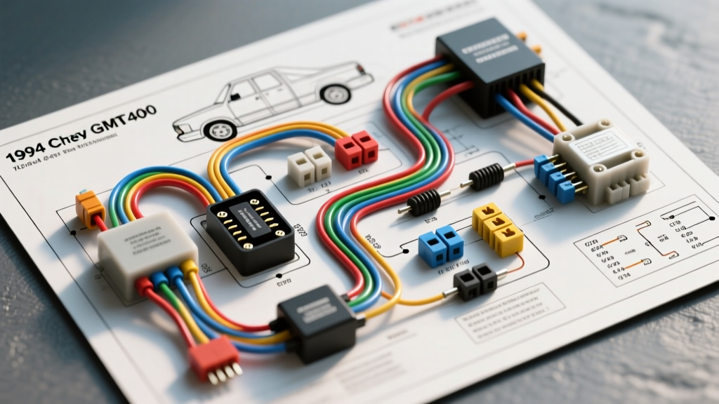
Introduction to the 1994 GMT400 Electrical Architecture
The 1994 Chevrolet C/K 1500, 2500, and 3500 trucks belong to the legendary GMT400 platform. For beginners and seasoned wrenches alike, the 1994 model year represents a unique transitional period in GM's electrical engineering. It features the mature iteration of the OBD-I (On-Board Diagnostics Generation I) system, predominantly utilizing Throttle Body Injection (TBI) on the 5.0L and 5.7L V8s, and Central Port Injection (CPI) on the 4.3L V6. Understanding how to read a 1994 Chevy truck wiring diagram free of expensive dealership subscriptions is the first step to mastering this robust, yet aging, electrical architecture.
Unlike modern CAN-bus networks where a single data wire controls multiple modules, the 1994 GMT400 relies on dedicated, point-to-point copper circuits. This makes it incredibly beginner-friendly for tracing faults, upgrading harnesses, or performing engine swaps. In this guide, we will break down the fundamental circuits, standard GM wire color codes, and real-world troubleshooting techniques using factory-accurate data.
Where to Find a 1994 Chevy Truck Wiring Diagram Free
Many beginners assume they need to purchase expensive factory service manuals (FSM) to access accurate schematics. While the physical Helms Inc. manuals are the gold standard, you can access a 1994 Chevy truck wiring diagram free through several authoritative channels:
- The GM Heritage Center: General Motors provides free digital access to historical service manuals and wiring schematics for older vehicles through their online archive.
- AutoZone Repair Guides: By registering for a free account on AutoZone's website, you can access Chilton and Haynes-based wiring diagrams specific to the 1994 C/K series.
- Third-Party Wiring Specialists: Companies like Painless Performance offer free, detailed PDF routing and wiring guides for GMT400 platforms to assist with their aftermarket harness installations.
Decoding GM Wire Color Codes & AWG Standards
Before tracing any circuit on your diagram, you must understand GM's standardized color-coding system. While aftermarket repairs may introduce splices and non-standard colors, a factory-intact 1994 Chevy truck will adhere to the following baseline. Furthermore, wire gauge (AWG) dictates the current-carrying capacity. According to SAE J1128 standards for low-tension primary cables, using the correct AWG is critical to preventing voltage drop and fire hazards.
| Wire Color | Standard Function | Typical AWG Size | Common Application |
|---|---|---|---|
| Orange | Constant Battery Feed (12V+) | 10 to 12 AWG | Main fuse box feeds, headlight switch input |
| Pink | Ignition Switched (12V+ in Run/Start) | 12 to 14 AWG | ECM power, radio, HVAC controls |
| Black | Chassis Ground | 12 to 16 AWG | Sensor grounds, module grounds, tail lights |
| Gray | Fuel Pump Feed | 12 to 14 AWG | Fuel pump relay to in-tank pump |
| Purple | Starter Solenoid Feed | 10 to 12 AWG | Ignition switch 'Start' position to starter |
| Dark Green / Tan | Headlight Feeds | 14 AWG | Left (Green) and Right (Tan) headlight circuits |
Real-World Troubleshooting: The Melting Headlight Switch
One of the most notorious failure points on the 1994 C/K truck is the headlight switch melting or failing prematurely. By looking at a free wiring diagram, you can easily see why: GM routed the entire amperage load of the headlights, parking lights, and tail lights directly through the mechanical contacts of the dash-mounted switch.
The Problem: The main battery feed to the switch is a 12 AWG Orange wire. The headlights draw roughly 5 to 7 amps each (approx. 24 amps total for all exterior lighting). Pushing 24+ amps through a 30-year-old mechanical switch creates immense resistance, heat, and eventual failure.
The Beginner-Friendly Fix (Relay Bypass): Using your diagram, you can design a relay bypass. Instead of the switch carrying the heavy load, use the switch's 14 AWG Dark Green and Tan output wires merely as a "trigger" signal (under 1 amp) for two standard 30A Bosch-style relays. Run new 10 AWG power feeds directly from the battery (via a 30A inline fuse) to the relays, and then to the headlights. This completely eliminates the voltage drop at the dash and saves the OEM switch.
TBI Engine Control Module (ECM) & ALDL Port Basics
If you are diagnosing a no-start condition or rough idle on a 5.7L TBI V8, you will need to interface with the ECM and the ALDL (Assembly Line Diagnostic Link) port located under the driver's side dash. The 1994 model uses the 12-pin ALDL connector (OBD-I), which is incredibly simple to read with a multimeter or a basic code reader.
| ALDL Pin | Wire Color | Function & Diagnostic Use |
|---|---|---|
| Pin A | Black/White | Ground. Essential for completing the diagnostic circuit. |
| Pin B | Tan/White | Serial Data Stream. Connects to ECM Pin E1 for scanning. |
| Pin M | Brown/White | Check Engine Lamp Control. Grounding this pin triggers the CEL. |
| Pin H | Gray | Fuel Pump Test. Applying 12V here bypasses the relay to test the pump. |
Reading Flash Codes: To read trouble codes without a scanner, use a paperclip to jump Pin A (Ground) to Pin B (Data). Turn the ignition to the "Run" position (do not start the engine). The Check Engine Light will flash Code 12 (one flash, pause, two flashes) to confirm diagnostic mode, followed by any stored fault codes (e.g., Code 15 for Coolant Temperature Sensor Low Voltage).
Fusible Links: The Hidden Circuit Protectors
When studying your 1994 Chevy truck wiring diagram free resources, you will notice symbols for "Fusible Links" near the starter solenoid and the main junction block on the firewall. Beginners often mistake these for standard wire and replace them with copper wire after a burnout, creating a massive fire hazard.
A fusible link is a specialized, high-temperature insulated wire that is exactly four AWG sizes smaller than the circuit it protects. For example, if the main alternator charge wire is 10 AWG, the fusible link protecting it will be 14 AWG. It is designed to melt internally and break the circuit during a dead short, while the outer silicone insulation remains intact to prevent a fire. Always replace blown fusible links with OEM-spec replacements or modern high-amperage ANL fuses, never standard copper wire.
Step-by-Step: Tracing a Parasitic Draw
A common issue on older GMT400 trucks is a dead battery after sitting for a few days. Here is how to use your wiring diagram and a digital multimeter (DMM) to trace a parasitic draw:
- Prep the Truck: Ensure all doors are closed, the glovebox light is off, and the under-hood light is disconnected or switched off.
- Set Up the DMM: Set your multimeter to the 10A (Amps) setting. Disconnect the negative battery terminal.
- Bridge the Circuit: Connect the red probe to the disconnected negative cable and the black probe to the negative battery post. Wait 30 minutes for the ECM and radio capacitors to enter "sleep" mode.
- Read the Baseline: A normal draw for a 1994 Chevy truck should be under 50 milliamps (0.05A). If it reads higher (e.g., 2.5A), you have a short.
- Pull Fuses: While watching the DMM, pull fuses one by one from the interior and engine bay fuse blocks. When the amperage drops to normal, you have found the faulty circuit.
- Consult the Diagram: Look up that specific fuse on your free wiring diagram to see exactly which components (e.g., courtesy lights, ECM memory, radio) are on that branch, and inspect those specific wires for chafing against the firewall or steering column.
Final Thoughts on GMT400 Wiring
The 1994 Chevrolet C/K truck represents an era of automotive electrical design that prioritized simplicity and mechanical reliability over complex multiplexing. By leveraging a 1994 Chevy truck wiring diagram free from reputable archives like the GM Heritage Center, understanding standard AWG requirements, and respecting the function of fusible links, even a beginner can confidently diagnose, repair, and upgrade their truck's electrical system. Always disconnect the battery before splicing wires, use crimp-and-seal heat shrink connectors instead of electrical tape, and verify your grounds—because on a GMT400, a bad ground is the root cause of 90% of all electrical gremlins.