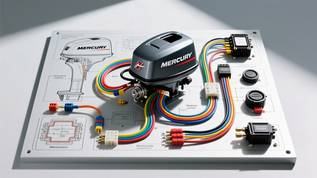
Introduction to Mercury Outboard Electrical Architecture
Understanding the complete wiring diagram for Mercury outboard motor systems is critical for diagnosing no-start conditions, erratic gauge behavior, and trim/tilt failures. While modern Mercury engines utilize Digital Throttle and Shift (DTS) multiplexing, the vast majority of marine technicians and DIYers are troubleshooting analog, carbureted, or early EFI (Electronic Fuel Injection) harnesses. These systems rely on a centralized main harness connecting the engine-mounted terminal block to the helm-side ignition switch, kill switch, and instrument panel.
Unlike automotive systems that utilize a centralized CAN-bus for basic starting and charging, traditional Mercury outboards use discrete, color-coded circuits for specific functions. The electrical architecture is divided into three primary sub-systems: the magneto/ignition trigger circuit, the 12V DC accessory and starting circuit, and the 3-phase AC charging circuit. Navigating these requires a strict adherence to Mercury marine wire color codes and an understanding of marine-specific environmental protections.
The Main Harness: AMP CPC and Deutsch Connectors
The physical connection between the boat harness and the outboard is typically handled by an AMP CPC (Circular Plastic Connector) on older models (usually 8-pin or 10-pin) or a sealed Deutsch DT series connector on newer EFI platforms. When consulting a wiring diagram for Mercury outboard motor applications, the pinout at this bulkhead connector is your primary diagnostic checkpoint.
Corrosion at the bulkhead connector is the number one cause of voltage drop in marine starting systems. Always apply a dielectric grease (such as Molykote 111) to the pins after testing. The 10 AWG red and black wires carrying the main battery current and ground must be inspected for green copper oxide creep, which increases resistance and starves the starter solenoid of the necessary amperage during cranking.
Core Ignition Switch Pinout and Wire Colors
The helm-side ignition switch is the nerve center of the outboard's starting sequence. A standard Mercury marine ignition switch utilizes a 6-pole configuration. Miswiring this switch is a common cause of dead batteries (due to parasitic draw) or fried rectifiers.
| Terminal | Function | Wire Color | AWG Size |
|---|---|---|---|
| B | Battery Positive (12V Constant) | Red | 10 AWG |
| I | Ignition (Switched 12V to ECU/CDI) | Purple | 14 AWG |
| S | Start (Trigger to Starter Solenoid) | Yellow/Red | 12 AWG |
| C | Choke / Fuel Enrichment | Brown/Yellow | 14 AWG |
| M | Magneto Kill (Ground to CDI) | Black/Yellow | 14 AWG |
| G | Ground / Illumination | Black | 14 AWG |
When the key is turned to the 'Start' position, the switch bridges the B (Red) and S (Yellow/Red) terminals, sending 12V to the engine-mounted starter solenoid. Simultaneously, the Purple (I) wire remains energized to power the ECU or CDI module. The Brown/Yellow (C) wire activates the primer solenoid or choke plate to enrich the fuel mixture for cold starts.
Stator, Rectifier, and Regulator Walkthrough
The charging system on a Mercury outboard begins at the stator, located under the flywheel. The stator generates a 3-phase Alternating Current (AC). According to standard Mercury wiring schematics, the stator outputs are identified by Yellow wires. These three Yellow wires route directly to the rectifier/regulator assembly.
The rectifier converts the 3-phase AC into Direct Current (DC), while the regulator clamps the voltage to a safe 14.2V to 14.4V to prevent overcharging the marine battery. The DC output leaves the rectifier via a Red wire (fused at 20A or 30A depending on the stator's amperage rating) and merges with the main battery positive circuit. The rectifier ground is achieved via a Black wire bolted directly to the engine block. A loose rectifier ground will cause AC ripple to enter the DC system, leading to erratic tachometer readings and premature bulb failure in the instrument panel.
Trim and Tilt Relay Circuit Analysis
The power trim and tilt system requires high amperage to actuate the hydraulic pump motor, typically drawing between 15 and 25 amps under load. Because the helm-side trim switch cannot handle this current, the wiring diagram utilizes a dual-relay setup.
- Red Wire (10 AWG): Constant 12V from the battery, protected by a 30A inline fuse or breaker.
- Black Wire (10 AWG): Main ground for the pump motor.
- Blue Wire (14 AWG): Trim UP signal from the helm switch to the 'Up' relay coil.
- Green Wire (14 AWG): Trim DOWN signal from the helm switch to the 'Down' relay coil.
When the helm switch is pressed 'Up', it sends 12V down the Blue wire, energizing the Up relay. This closes the high-amperage contacts, sending battery voltage to the Blue wire at the pump motor, while the Green wire at the motor acts as the ground path. Reversing the switch reverses the polarity at the motor.
Troubleshooting the Trim Limit Switch
Many Mercury outboards feature a trim limit switch designed to cut power to the 'Up' relay when the engine reaches a dangerous tilt angle (usually around 30 degrees) to prevent the propeller from ventilating. This switch is wired in series with the Blue (Up) wire. If your outboard will trim down but refuses to trim up, bypass the trim limit switch at the engine cowl connector to isolate a failed micro-switch or a severed wire in the tilt tube.
Safety Lanyard (Kill Switch) Integration
The emergency engine shut-off (kill switch) is a critical safety device mandated by marine safety authorities. In the Mercury wiring diagram, the kill switch interacts directly with the Black/Yellow magneto kill wire. When the lanyard is pulled, the switch closes the circuit, connecting the Black/Yellow wire to the Black (Ground) wire.
This provides a direct ground path to the primary winding of the ignition coil or the CDI module, instantly collapsing the magnetic field and stopping spark production. If an engine refuses to produce spark, the first diagnostic step is to disconnect the Black/Yellow wire at the engine terminal block. If spark returns, the fault lies in the boat-side kill switch or a chafed Black/Yellow wire grounding out against the steering cable.
Expert Troubleshooting: Voltage Drop and Ground Paths
When using a wiring diagram for Mercury outboard motor diagnostics, a multimeter set to DC Voltage is your best tool. Never rely solely on continuity tests for high-amperage circuits, as a single strand of 10 AWG wire will show continuity even if the other 99 strands are corroded.
- Starter Solenoid Voltage Drop: Place your red probe on the battery positive post and your black probe on the solenoid input stud while cranking. A reading above 0.5V indicates excessive resistance in the main battery cable or a corroded battery switch.
- Ground Circuit Testing: Place the red probe on the engine block and the black probe on the battery negative post while cranking. Any reading above 0.2V confirms a poor engine-to-battery ground path, often caused by paint or corrosion on the transom grounding stud.
- Ignition Switch Feed: Probe the Purple (I) wire at the engine terminal block while the key is in the 'Run' position. It must read within 0.5V of the battery's resting voltage. A lower reading indicates a failing ignition switch or corroded bulkhead pins.
Marine Wire Standards and Best Practices
Automotive wire (SAE J1128) is strictly prohibited for use in marine outboard harnesses due to the highly corrosive saltwater environment. When repairing or extending any circuit found in the Mercury wiring diagram, you must use marine-grade, tinned copper wire that meets SAE J1171 and UL 1426 standards. The tin coating prevents copper oxide formation, which wicks up the wire jacket via capillary action and destroys circuits from the inside out.
Furthermore, all connections must be sealed using adhesive-lined heat shrink tubing. Standard vinyl electrical tape will degrade and unwrap when exposed to UV light and marine solvents. For comprehensive schematic archives and bulkhead pinout references, marine technicians frequently consult the ContinuousWave Whaler Reference database, which remains one of the most exhaustive repositories of legacy Mercury and OMC harness diagrams available. Always cross-reference your specific engine serial number with the United States Coast Guard (USCG) Marine Safety Center guidelines to ensure your electrical modifications remain compliant with federal ignition protection and overcurrent safety standards.