Understanding the 3-Wire AC Pressure Switch Architecture
When technicians and DIYers search for a wiring diagram how to jump 3 wire ac pressure switch, they are usually facing a non-engaging AC compressor clutch and are looking for a quick bypass to test the system. However, blindly jumping wires on a modern 3-wire HVAC pressure sensor is one of the fastest ways to destroy a Powertrain Control Module (PCM) or HVAC control head. To diagnose the system safely, you must first understand that not all 3-wire switches are created equal. They generally fall into two distinct categories: the modern Linear Pressure Transducer and the legacy Mechanical Dual-Stage (Trinary) Switch.
According to diagnostic standards outlined by MotorAge, approximately 90% of vehicles manufactured after 2004 utilize a 3-wire pressure transducer rather than a mechanical switch. A transducer does not simply open or close a circuit; it sends a variable analog voltage signal to the PCM, which then calculates the exact refrigerant pressure and decides whether to engage the compressor clutch relay. Jumping the wires on a transducer will not engage the compressor and will likely short the 5-volt reference bus, taking down critical engine sensors like the TPS and MAP alongside the AC system.
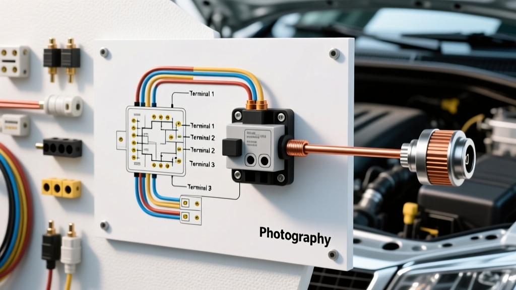
Wiring Diagram & Pinout: The 3-Wire Pressure Transducer (Modern)
The modern 3-wire AC pressure transducer (common on GM, Ford, Chrysler, and most Asian imports) uses a Delphi Metri-Pack 150 or Weather-Pack connector. It relies on a 5-volt reference, a signal return, and a low-reference ground. Below is the standard specification chart for this architecture.
| Pin / Cavity | Function | Typical Wire Color (GM/Ford) | Wire Gauge (AWG) | Voltage Spec |
|---|---|---|---|---|
| Pin A (or 1) | 5-Volt Reference (VREF) | Red/White or Gray | 18 or 20 AWG | 4.8V - 5.2V (Key On) |
| Pin B (or 2) | Signal Return to PCM | Yellow or Light Blue | 18 or 20 AWG | 0.5V (0 psi) to 4.5V (450+ psi) |
| Pin C (or 3) | Low Reference (Ground) | Black/White or Solid Black | 18 or 20 AWG | Less than 0.05V drop to battery neg |
The Danger of Jumping a Transducer
If you attempt to bypass a 3-wire transducer by inserting a jumper wire between Pin A (5V Reference) and Pin B (Signal), you are feeding 5 volts directly into a PCM analog-to-digital converter circuit that may not be rated for continuous high-voltage saturation. Worse, if you accidentally jump Pin A to Pin C (Ground), you create a dead short on the PCM's 5V reference bus. The PCM will immediately detect the short, shut down the 5V supply to protect itself, and set codes like P0642 (Sensor Reference Voltage A Circuit Low). Your AC compressor will remain disabled, and the vehicle may enter limp mode because the throttle position and MAP sensors share that same 5V bus.
Wiring Diagram & Pinout: 3-Wire Mechanical Dual-Stage Switch (Legacy)
On older vehicles (typically pre-2005 Ford, some older European models, and specific heavy-duty truck applications), the 3-wire switch is a mechanical dual-stage device. It contains two separate internal diaphragms: one for low-pressure cutoff and one for high-pressure cutoff. This switch acts as a true series circuit interrupter and can be jumped for diagnostic purposes.
| Pin / Cavity | Function | Typical Wire Color | Wire Gauge (AWG) | Testing / Jumping Procedure |
|---|---|---|---|---|
| Pin 1 | 12V Power In (from HVAC Relay/Fuse) | Red or Light Green | 16 AWG | Verify 12V with Key On, AC On. |
| Pin 2 | 12V Power Out (Low Side / Compressor) | White or Black/Yellow | 16 AWG | Jump to Pin 1 to bypass low-pressure cutoff. |
| Pin 3 | 12V Power Out (High Side / Fan Override) | Dark Green or Orange | 16 AWG | Do not jump for compressor testing. |
How to Safely Jump a Mechanical 3-Wire Switch
If your wiring diagram confirms you are dealing with a mechanical dual-stage switch (verify by checking if Pin 1 has 12V battery voltage, not 5V), you can safely jump the circuit to test the compressor clutch coil and relay. Use a heavy-duty fused jumper wire (rated for at least 10 amps) to bridge Pin 1 and Pin 2. If the compressor clutch engages when jumped, your electrical circuit downstream is healthy, and the issue is either a failed mechanical switch or a refrigerant charge issue. Never leave the jumper wire installed during driving, as you will bypass the low-pressure safety cutoff, risking catastrophic compressor seizure if a leak occurs.
Proper Diagnostic Procedure: Back-Probing the Transducer
Instead of searching for a way to jump a modern transducer, professional technicians use a digital multimeter (DMM) and T-pins to back-probe the connector while it is plugged in. According to Delphi Technologies connector specifications, piercing the wire insulation with standard test probes can allow moisture ingress, leading to green rot and future failures. Always use proper back-probing T-pins inserted into the rear of the Metri-Pack 150 connector.
- Verify the 5V Reference: Turn the ignition to the ON position (engine off). Back-probe Pin A. You should read between 4.8V and 5.2V. If you read 0V, check for an open circuit or a shared 5V bus short elsewhere in the engine bay.
- Verify the Ground Circuit: Back-probe Pin C. Switch your DMM to measure voltage. Place the red lead on the battery positive terminal and the black lead on Pin C. You should read battery voltage (approx. 12.6V), confirming the PCM ground path is intact. Alternatively, measure resistance to a known good chassis ground (should be less than 0.5 ohms).
- Read the Signal Voltage: Back-probe Pin B. With the system fully charged and static (engine off, ambient temperature equalized), the voltage should read between 1.0V and 1.5V (representing roughly 60-90 psi of static R134a pressure). If the signal reads 0.1V or less, the PCM interprets this as 0 psi and will disable the compressor relay to prevent damage. If the signal reads 4.8V+, the PCM sees an over-pressure condition and will also inhibit the clutch.
- Correlate with Scan Tool Data: Compare your DMM voltage on Pin B to the AC Pressure Sensor PID on a bi-directional OBD2 scan tool. The scan tool should translate the voltage into a PSI or kPa reading that matches your manifold gauge set.
Real-World Failure Modes & Harness Chafing Points
When the wiring diagram indicates a healthy circuit but the compressor remains disabled, physical harness damage is the most common culprit. The AC pressure switch is mounted on the high-pressure line, usually near the condenser or the firewall, exposing it to extreme heat, vibration, and road debris.
- Condenser Fan Chafing: On many front-wheel-drive platforms, the pressure switch harness is routed dangerously close to the condenser cooling fan shroud. Over time, vibration wears through the 18 AWG wire loom, causing the Signal Return wire to short against the grounded fan motor housing. This pulls the signal voltage to 0V, tricking the PCM into a low-pressure inhibit state.
- Metri-Pack 150 Weather Seal Failure: If the secondary lock (red plastic retainer) on the connector is missing or broken, the terminals can back out slightly. This compromises the silicone weather seal, allowing water and road salt to enter the cavity. This causes galvanic corrosion (green rot) on the copper alloy terminals, increasing resistance on the 5V reference line and causing erratic compressor cycling.
- Pigtail Pigtail Overheating: On legacy 12V mechanical switches, the internal contacts can develop high resistance over years of arcing. This resistance generates heat, melting the plastic connector housing near Pin 1 and Pin 2. If the plastic is discolored or brittle, the entire switch and connector pigtail must be replaced and solder-sealed; simple crimp connectors will fail again due to the under-hood thermal cycling.
Summary: Bypass vs. Diagnose
Understanding the wiring diagram how to jump 3 wire ac pressure switch requires knowing exactly which generation of HVAC system you are working on. If you have a 5V transducer, put the jumper wire away and grab your multimeter and scan tool. If you have a 12V mechanical switch, a fused jumper between the power-in and power-out pins is a valid, safe diagnostic step. Always reference OEM-specific pinouts, as wire colors vary wildly between manufacturers, but the fundamental architecture of the 5V reference, signal, and ground remains universal across modern automotive electrical networks. For deeper electrical diagnostic standards, refer to the SAE International J1113 guidelines for vehicle component electromagnetic compatibility and circuit protection.