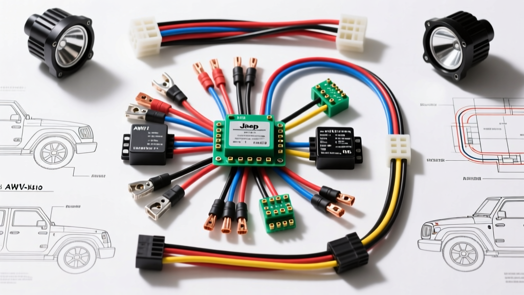
Understanding the Wiring Diagram for Pot Lights in Off-Road Applications
In the automotive, marine, and heavy-truck sectors, the term 'pot lights' refers to flush-mounted or recessed LED pod lights. Whether you are embedding 3-inch LED pods into a custom Jeep Wrangler JL grille, recessing them into the bumper of a Ford Super Duty, or wiring marine deck lights, the electrical principles remain identical. Unlike surface-mounted light bars, recessed pot lights are notoriously difficult to access once installed. Therefore, getting the wiring diagram for pot lights correct—and knowing how to troubleshoot the circuit before sealing the housings—is critical. This guide provides a comprehensive, step-by-step troubleshooting flow based on a standard Bosch-style relay circuit triggered by a factory auxiliary (AUX) switch bank or aftermarket upfitter switches.
Core Schematic: Relay-Based Wiring Diagram for Pot Lights
Before diving into diagnostics, you must understand the baseline schematic. A proper wiring diagram for pot lights utilizes a 4-pin ISO mini-relay to isolate the high-current draw of the LED pods from the low-current trigger circuit of the vehicle's factory AUX switches. Directly wiring high-draw lights to factory switch outputs will melt the OEM wiring harness and blow the BCM (Body Control Module) fuses.
- Pin 30 (Main Power): 10 AWG wire routed directly from the positive battery terminal, protected by a 30A ATO blade fuse within 18 inches of the battery post.
- Pin 87 (Load Output): 10 AWG wire routed to the positive input of the recessed LED pot lights.
- Pin 86 (Trigger Input): 16 AWG wire connected to the factory AUX switch output (e.g., Jeep JL AUX 1, which provides a 12V+ signal when toggled via the Uconnect system).
- Pin 85 (Ground): 16 AWG wire secured to a clean, bare-metal chassis ground point, ideally utilizing a ring terminal and a star washer to bite through the factory e-coat paint.
Step-by-Step Troubleshooting Flowchart
When your recessed LED pods fail to illuminate, avoid the temptation to immediately pull the lights out of their recessed housings, which can damage the seals or scratch the bumper. Instead, use a digital multimeter (DMM) and follow this systematic diagnostic flow to isolate the fault.
Phase 1: Symptom - Pot Lights Fail to Illuminate
Step 1: Verify Main Power at Pin 30
Set your DMM to DC Voltage. Place the red probe on the wire entering Relay Pin 30 and the black probe on a known good ground. You should read 12.2V to 12.6V (engine off) or 13.8V to 14.4V (engine running). If you read 0V, inspect the inline 30A ATO fuse and check for a broken 10 AWG wire between the battery and the relay. According to SAE J1128 standards, 10 AWG primary cable is required for continuous loads up to 30 amps to prevent thermal degradation.
Step 2: Verify AUX Trigger at Pin 86
With the vehicle's ignition in the 'Run' position, toggle the AUX switch to 'ON' via the dash or infotainment screen. Probe the wire at Relay Pin 86. You must see 12V+. If the voltage is absent, the issue lies upstream. In a Jeep JL, verify the AUX switch configuration in the Uconnect settings menu to ensure the specific switch is enabled and not set to 'Momentary' or 'Off'. For more on factory integration, refer to the Mopar Auxiliary Switch Technical Guidelines.
Step 3: Verify Ground Integrity at Pin 85
A missing ground will prevent the relay coil from energizing. Set your DMM to Continuity mode. Disconnect the relay, place one probe on the Pin 85 wire terminal and the other on the negative battery post. You should hear a tone indicating less than 1 ohm of resistance. If there is no continuity, clean the chassis ground point. Torque the M6 ground bolt to 10 Nm to ensure a vibration-proof connection.
Step 4: Verify Output at Pin 87
If the relay clicks but the pot lights remain dark, probe the wire at Pin 87 while the relay is energized. If you have 12V+ at Pin 87 but the lights are off, the fault is downstream. Proceed to Phase 2.
Phase 2: Symptom - Pot Lights Flicker or Operate Dimly
Dim or flickering recessed lights almost always indicate a voltage drop or an inadequate ground path, rather than a dead short. Because pot lights are often mounted in composite bumpers or fiberglass fenders, finding a true chassis ground near the light housing is difficult.
Voltage Drop Testing: Set your DMM to DC Voltage. Place the red probe on the positive battery terminal and the black probe on the positive input terminal of the LED pot light (with the circuit energized). A reading above 0.5V indicates excessive resistance in the 10 AWG positive feed. Next, test the ground side: place the red probe on the negative battery terminal and the black probe on the negative input terminal of the light. A reading above 0.2V indicates a poor ground connection. Run a dedicated 10 AWG ground wire back to the battery negative or a verified chassis ground if the drop is too high.
Phase 3: The PWM Dimming Trap
Modern vehicles, including the Jeep Wrangler JL and Ford Super Duty, often use Pulse Width Modulation (PWM) on their AUX switches to allow for dimming. If your recessed pot lights do not feature PWM-compatible LED drivers, the rapid pulsing of the 12V signal will cause the lights to strobe, flicker, or fail to turn on entirely. If you suspect a PWM issue, wire a PWM filter capacitor (typically 4700µF) in parallel across the positive and negative leads at the light housing, or reconfigure the AUX switch in the vehicle settings to 'Battery' mode, which provides a steady 12V output.
Wire Gauge, Pinout, and Component Specifications
| Circuit Segment | Relay Pin | Wire Gauge (AWG) | Fuse Rating | Connector Type |
|---|---|---|---|---|
| Main Battery Feed | 30 | 10 AWG | 30A ATO Blade | Ring Terminal (Heat Shrink) |
| Load to Pot Lights | 87 | 10 AWG | N/A (Protected by Main) | Deutsch DT 2-Pin |
| AUX Switch Trigger | 86 | 16 AWG | 5A Add-A-Circuit | Weather-Pack / Posi-Tap |
| Chassis Ground | 85 | 16 AWG | N/A | Ring Terminal w/ Star Washer |
Connector Selection for Recessed Pot Lights
When executing a wiring diagram for pot lights, connector selection is paramount. Because these lights are flush-mounted, water and road grime tend to pool around the rear of the housing. Standard spade terminals or uninsulated butt connectors will corrode within months, leading to high-resistance faults. Always use sealed Deutsch DT or Weather-Pack connectors with silicone sealing plugs. Apply dielectric grease to the pins before mating to prevent galvanic corrosion, especially in marine or winter road-salt environments.
Common Failure Modes in Recessed Installations
Thermal Throttling: Recessed pot lights lack the ambient airflow of surface-mounted pods. If the LED driver overheats, it will internally throttle the amperage draw, resulting in dim lights. Ensure the housing features adequate rear heat-sinking and avoid wrapping the rear of the light in sound-deadening material.
Ground Loop Interference: If your pot lights share a ground point with high-current accessories like a winch or air compressor, the voltage spike can backfeed into the LED drivers, destroying them. Always use an isolated ground stud or run a dedicated ground directly to the battery negative terminal.