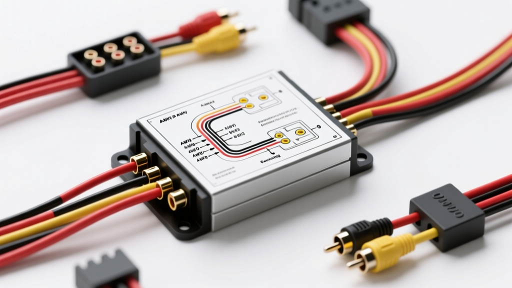
Introduction to Car Audio Electrical Flow
Understanding a car amplifier wiring diagram is the first step toward achieving high-fidelity mobile audio without compromising your vehicle's electrical system. Unlike home audio systems that rely on standardized 120V AC wall power, automotive electrical systems operate on a 12V DC (Direct Current) architecture. This fundamental difference means that car amplifiers require massive current (amperage) to produce high wattage, making the wiring diagram a critical blueprint for safety and performance.
For beginners, a factory or aftermarket amplifier schematic can look like a maze of lines, symbols, and color codes. However, every car amplifier wiring diagram boils down to five primary circuits: constant 12V power, chassis ground, remote turn-on trigger, audio signal inputs (RCA or speaker-level), and speaker outputs. Mastering these fundamentals will allow you to install, troubleshoot, and upgrade any mobile audio system with professional confidence.
Decoding Schematic Symbols and Wire Colors
Before cutting or crimping any wire, you must learn to read the standard symbols used in automotive electrical schematics. Most diagrams adhere to standards set by the SAE International J1128 guidelines for low-tension primary cables.
Power and Ground Identifiers
- B+ (Battery Positive): Typically represented by a solid line connected to a battery symbol. In aftermarket harnesses, this is universally a thick yellow or red wire.
- GND (Chassis Ground): Represented by a symbol resembling an upside-down pitchfork or three descending horizontal lines. The ground wire is almost always black.
- Fuse Symbols: Shown as a small rectangle or an 'S' curve on the B+ line, indicating the placement of an ANL, AGU, or MIDI fuse.
Signal and Trigger Lines
- REM (Remote Turn-On): Usually depicted as a dashed line or a line with a switch symbol. In standard ISO 10487 head unit connectors, this is pin 5 or 7, utilizing a blue or blue/white stripe 18-AWG wire.
- RCA Inputs: Represented by shielded coaxial symbols. They carry unbalanced, low-voltage (2V to 5V) preamplified audio signals.
Wire Gauge (AWG) and Current Capacity Chart
The most critical aspect of any car amplifier wiring diagram is selecting the correct American Wire Gauge (AWG). Using wire that is too thin results in severe voltage drop, causing the amplifier to enter 'protect mode' or overheat. When sourcing wire, always insist on OFC (Oxygen-Free Copper) rather than CCA (Copper-Clad Aluminum). CCA wire has up to 30% higher electrical resistance and is prone to corrosion and snapping under vibration.
Refer to the specification chart below to match your amplifier's total RMS wattage and current draw to the correct OFC wire gauge and primary fuse size.
| Total Amp RMS Wattage | Max Current Draw (Approx.) | Recommended OFC Wire Gauge | Main Fuse Type & Rating |
|---|---|---|---|
| Up to 400W | 35A - 45A | 8 AWG | 50A AGU or ATC |
| 400W - 800W | 45A - 80A | 4 AWG | 80A ANL or MIDI |
| 800W - 1500W | 80A - 150A | 1/0 AWG (0-Gauge) | 150A ANL |
| 1500W - 2500W+ | 150A - 250A+ | 2/0 AWG or Multiple Runs | 250A+ ANL / Class-T |
Note: Current draw is calculated assuming a Class D amplifier efficiency of 80% at 12.5V. Class AB amplifiers operate at roughly 50-60% efficiency and will require heavier gauge wire for the same RMS wattage.
Step-by-Step: Tracing the Power and Ground Circuits
Battery to Amplifier (+12V Constant)
The B+ circuit begins at the vehicle's positive battery terminal. According to Mobile Electronics Certification Program (MECP) best practices, the main inline fuse must be installed within 18 inches of the battery positive post. This protects the entire length of the power wire in the event of a short circuit against the vehicle's chassis. The wire should be routed through an existing firewall grommet, avoiding sharp metal edges and high-heat zones like the exhaust manifold.
The Chassis Ground Connection
A car amplifier wiring diagram will show the ground wire terminating at the chassis. The vehicle's steel unibody acts as the return path to the battery's negative terminal. For a flawless ground, you must remove all paint, primer, and rust down to bare, shiny metal using a wire brush or sanding disc. Use a heavy-duty, closed-end ring terminal crimped with a hex-crimp tool, and secure it with a self-tapping sheet metal screw or an existing factory bolt torqued to OEM specifications. A poor ground is the number one cause of alternator whine and thermal clipping.
The Remote Turn-On (REM) Trigger Circuit
The REM terminal on your amplifier requires a +12V signal to wake up the internal power supply. This signal is provided by the aftermarket stereo's 'Amp Turn-On' wire (blue/white). Because this circuit is typically limited to 300mA (milliamps) of current, it can only safely trigger one or two amplifiers.
If your wiring diagram includes multiple amplifiers, a DSP (Digital Signal Processor), or cooling fans, you must integrate a 30A SPDT (Single Pole Double Throw) Bosch-style relay. The head unit's blue/white wire triggers the relay coil (Pins 85 and 86), while the relay's internal switch (Pins 30 and 87) routes heavy current directly from the fused B+ distribution block to the REM terminals of all connected devices.
Signal Inputs: RCA vs. Speaker Level Wiring
Car audio signal wiring is highly susceptible to Electromagnetic Interference (EMI) and Radio Frequency Interference (RFI) generated by the alternator, ignition coils, and fuel injectors.
RCA (Low-Level) Inputs
RCA cables carry unbalanced audio signals. To prevent alternator whine, RCA cables must be routed down the opposite side of the vehicle from the B+ power wire. If the signal and power cables must cross, they should intersect at a strict 90-degree angle to minimize inductive coupling. Always use high-quality, shielded twisted-pair RCA cables with tight, corrosion-resistant ground rings.
Speaker-Level (High-Level) Inputs
If your factory head unit lacks RCA pre-outs, your amplifier wiring diagram will utilize high-level inputs. These circuits tap directly into the factory speaker wires. The amplifier uses internal summing resistors and step-down transformers to convert the high-voltage speaker signal (up to 40V in some premium factory amplified systems) down to a usable line-level voltage. Always use a multimeter to identify the positive and negative factory speaker wires before splicing to avoid out-of-phase audio cancellation.
Common Beginner Wiring Mistakes and Troubleshooting
Even with a perfect car amplifier wiring diagram, installation errors can lead to system failure. Use a Digital Multimeter (DMM) to perform these diagnostic checks if your amplifier fails to power on or enters protect mode:
- The Voltage Drop Test: With the engine running and the volume turned up, measure the DC voltage directly at the amplifier's B+ and GND set-screw terminals. If the reading drops below 11.5V, you have an undersized power wire, a poor ground connection, or a failing alternator.
- Alternator Whine (Ground Loops): If you hear a high-pitched whine that rises with engine RPM, you have a ground loop. This occurs when the head unit and the amplifier are grounded to different points with varying resistance. Ensure both are grounded to the same heavy-gauge chassis point, or install a ground loop isolator on the RCA lines.
- Protect Mode (Short Circuit): Disconnect all speaker wires and RCA cables. If the amplifier powers on normally, the fault lies in the speaker wiring. Check for pinched speaker wires touching the chassis, or verify that your subwoofer's final impedance matches the amplifier's stable ohm rating (e.g., wiring a 2-ohm sub to a 4-ohm stable amp will trigger thermal protection).
Authoritative References
For further technical specifications on automotive wiring standards and mobile electronics installation, consult the following resources: