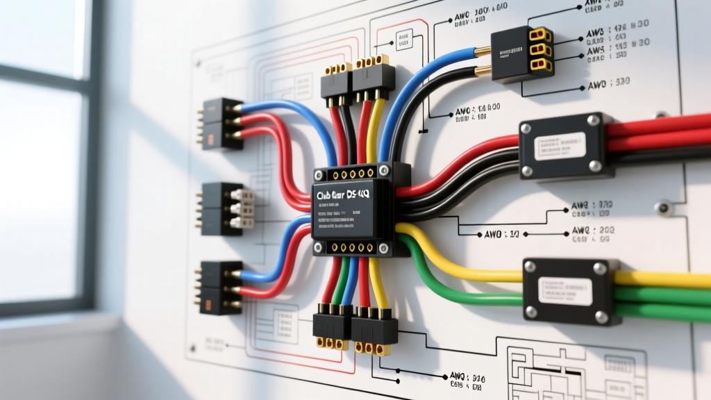
Introduction to the Club Car DS 48V IQ Electrical Architecture
When diagnosing or modifying a golf cart, having an accurate club car ds wiring schematic is the difference between a quick fix and a fried controller. Introduced in the early 2000s, the 48V IQ (Intellectual Quotient) system replaced the older 36V series-wound setups, introducing separately excited (SepEx) motors, regenerative braking, and computerized motor control via the Curtis 1268 controller. Unlike older resistor-based speed controls, the IQ system relies on a complex network of low-voltage signal wires, hall-effect sensors, and an On-Board Charger (OBC) that dictates charging logic and tow/run states.
This technical reference provides the exact wire color codes, AWG specifications, and controller pinouts required to troubleshoot the 48V IQ traction and charging circuits. Whether you are dealing with a solenoid that refuses to engage or a regenerative braking failure, understanding the precise signal paths outlined below is mandatory for safe and effective repairs.
Main Wiring Harness Color Codes & AWG Specifications
The Club Car DS IQ harness is divided into two primary domains: the high-current traction circuit (which handles upwards of 300+ amps under peak load) and the low-current control circuit (which operates between 5V and 48V). According to SAE J1128 standards for low-tension primary cable, wire gauge must be selected based on both current draw and physical routing length to prevent voltage drop.
| Circuit Function | Wire Color | AWG Size | Connector Type | Max Current / Voltage |
|---|---|---|---|---|
| B+ (Main Battery Positive) | Red | 6 AWG (or 4 AWG) | 5/16' Ring Terminal | 350A Peak / 48V DC |
| B- (Main Battery Negative) | Black | 6 AWG (or 4 AWG) | 5/16' Ring Terminal | 350A Peak / 48V DC |
| M- (Motor Armature Return) | Black w/ Yellow Stripe | 6 AWG | 5/16' Ring Terminal | 300A Peak |
| Solenoid Coil Positive | Red w/ White Stripe | 18 AWG | Spade / Amp Connector | 2A / 48V DC |
| Solenoid Coil Negative | Yellow w/ White Stripe | 18 AWG | Spade / Amp Connector | 2A / Controller Ground |
| Key Switch Input | Yellow | 16 AWG | Molex / Deutsch | 500mA / 48V DC |
| Throttle Signal (PB-6/MCOR) | White | 18 AWG | Molex 3-Pin | 10mA / 0-5V Analog |
| Forward / Reverse Switch | Blue (Fwd) / Orange (Rev) | 16 AWG | Microswitch Spade | 500mA / 48V DC |
High-Current Traction Circuit Notes
Factory 6 AWG battery cables are sufficient for stock setups, but if your DS is equipped with lifted suspensions, larger off-road tires, or a high-torque aftermarket motor, upgrading the main B+, B-, and M- cables to 4 AWG or 2 AWG flexible welding cable is highly recommended. This reduces resistance and prevents the insulation from melting during prolonged hill climbs where amperage can sustain above 150A.
Curtis 1268 Controller Pinout Configuration
The heart of the IQ system is the Curtis 1268 SepEx motor controller. As documented in the Curtis Instruments technical manuals, the controller utilizes two main connectors: J1 (Control/Logic) and J2 (High Current/Motor). Incorrectly probing or back-probing these pins with a standard test light can destroy the internal logic board. Always use a high-impedance digital multimeter (DMM).
| Pin Number (J1) | Function | Input/Output | Signal Type & Expected Values |
|---|---|---|---|
| J1-1 | B+ Main Power | Input | 48V DC (Constant from Battery) |
| J1-2 | Key Switch | Input | 48V DC (Only when Key is ON) |
| J1-3 | Forward Switch | Input | 48V DC (Engaged in Forward) |
| J1-4 | Reverse Switch | Input | 48V DC (Engaged in Reverse, Buzzer Active) |
| J1-5 | Throttle High | Input | 0.8V (Pedal Up) to 3.3V (Pedal Down) |
| J1-6 | Throttle Low | Input | Analog Ground Reference |
| J1-7 | HPD (High Pedal Disable) | Input | 48V DC (Microswitch in F/R or Throttle Box) |
| J1-16 | Solenoid Driver | Output | Ground Path (Pulls low to engage solenoid) |
Forward/Reverse Switch and Throttle Sensor Wiring
The F/R Microswitch Assembly
The Forward/Reverse switch on the Club Car DS is not merely a mechanical polarity reverser; it is a logic input for the Curtis controller. Inside the F/R housing, you will find two microswitches. When the lever is pushed forward, the Blue wire receives 48V from the key switch and sends it to J1-3. When pulled backward, the Orange wire sends 48V to J1-4, which also triggers the reverse warning buzzer circuit. A common failure point is the physical cam inside the F/R housing wearing down, failing to depress the microswitch plunger fully, resulting in a 'dead pedal' condition despite good wiring.
PB-6 vs. MCOR Throttle Assemblies
Early IQ models (2001-2007) utilized the PB-6 throttle box, which contains a potentiometer and an inductive roll sensor. The PB-6 is notorious for internal wiper wear, causing erratic voltage spikes that put the Curtis controller into a protective fault mode (indicated by the tow/run switch flashing). In 2008+, Club Car transitioned to the MCOR (Motor Controller Output Regulator), a non-contact hall-effect sensor that eliminated the physical wiper track. When reading the white signal wire on a PB-6, you should see a smooth linear sweep from roughly 0.8V to 3.3V. If you see sudden drops to 0V mid-sweep, the PB-6 must be replaced or upgraded to an MCOR conversion kit.
On-Board Charger (OBC) Wiring & Lockout Logic
The OBC is a highly integrated component that monitors battery voltage, controls the charge rate, and operates a lockout relay that prevents the cart from being driven while plugged in. The OBC connects to the main harness via a 6-pin AMP connector.
- Pin 1 (AC Hot): 110V AC Input from charge receptacle.
- Pin 2 (AC Neutral): 110V AC Return.
- Pin 3 (B+): 48V DC Positive sensing and power.
- Pin 4 (B-): 48V DC Negative sensing.
- Pin 5 (Charge Signal): Sends a low-voltage signal to the controller to disable the solenoid during charging.
- Pin 6 (Ground/Signal): Logic ground.
Troubleshooting Tip: If your cart will not move and the solenoid does not click, but the batteries are fully charged, unplug the 6-pin OBC connector. Use a jumper wire to bypass the OBC lockout relay (connecting the harness side B+ directly to the solenoid coil feed). If the cart suddenly operates, the OBC's internal relay has failed, a very common issue on aging DS models.
Common Failure Modes & Diagnostic Testing
Symptom: Solenoid Clicks but Cart Will Not Move
This indicates that the low-current control circuit is successfully triggering the solenoid coil, but high-current traction power is either not reaching the motor or the controller is faulting out immediately.
- Test the Solenoid Large Terminals: Set your DMM to DC Voltage. Place the black probe on the battery negative and the red probe on the motor-side large terminal of the solenoid. Press the pedal. You should read full pack voltage (approx. 48V-50V). If you read 0V, the solenoid internal contacts are burnt and must be replaced.
- Check the M- Cable: Inspect the Black/Yellow wire running from the controller to the motor. Vibration often causes the ring terminal to loosen at the motor stud, creating high resistance and arcing.
- Read Controller Fault Codes: Turn the key on, press the pedal, and observe the Tow/Run switch LED or the V-Glide meter. The Curtis controller will flash a specific sequence (e.g., 3 flashes, pause, 2 flashes) indicating a specific fault like 'HPD Active' or 'Throttle Out of Range'.
Symptom: No Solenoid Click, Cart Completely Dead
When the solenoid fails to engage, the issue lies in the logic circuit or the safety interlocks.
- Verify Tow/Run Switch Position: Ensure the toggle switch under the seat is in the 'Run' position. If the switch is faulty, it will not complete the ground path required for the controller to wake up.
- Test the Key Switch: Probe the Yellow wire at the controller J1-2 pin. If you do not have 48V when the key is turned, trace the circuit back through the dash and check the inline 10A fuse located near the positive battery terminal.
- Inspect the F/R Microswitches: The Curtis controller requires a valid HPD (High Pedal Disable) signal. If the microswitch in the F/R housing is misadjusted or broken, the controller will refuse to fire the solenoid to prevent the cart from lurching unexpectedly upon key-on.
Summary of Best Practices
When working with any club car ds wiring schematic, always disconnect the main battery negative and ensure the Tow/Run switch is in the 'TOW' position before unplugging any controller or motor wires. The SepEx motor field windings can generate severe inductive voltage spikes if disconnected while under load or while the capacitors in the Curtis 1268 are fully charged, which will instantly destroy the controller's internal MOSFETs. Use dielectric grease on all low-voltage Molex connectors to prevent corrosion in outdoor storage environments, and always torque high-amperage ring terminals to 120 in-lbs to prevent thermal runaway at the connection points.