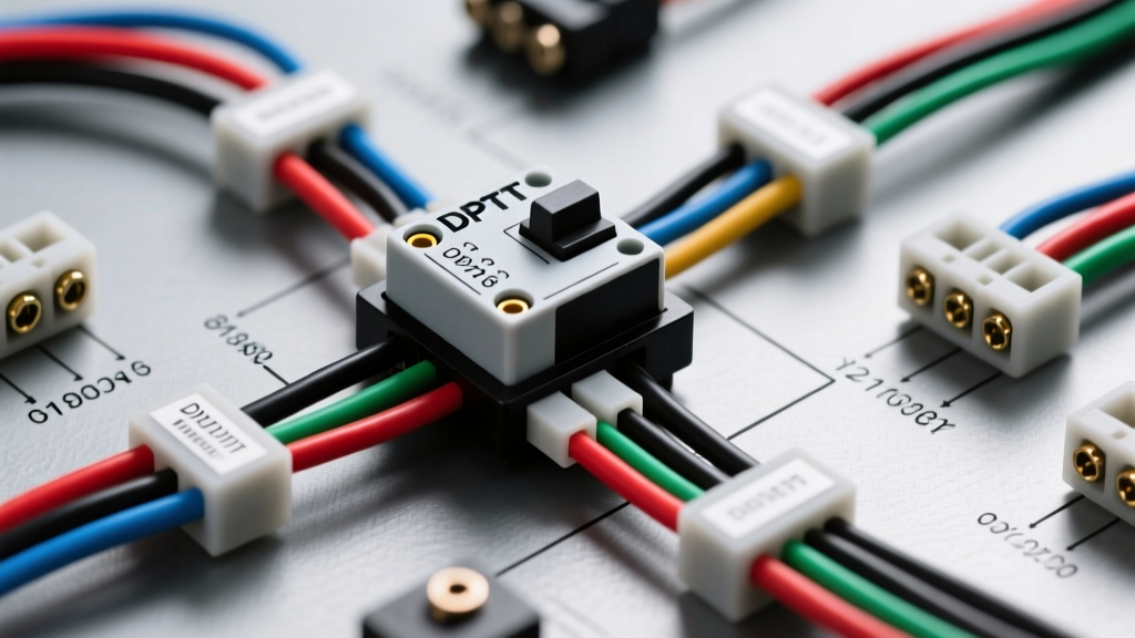
Understanding the DPDT Switch in Automotive Electrical Systems
When integrating custom DC motors into a vehicle—such as auxiliary linear actuators for motorized tonneau covers, custom HVAC blend doors, off-road rocker panel steps, or marine winches—controlling the direction of the motor is paramount. Unlike AC motors, reversing a DC motor requires reversing the polarity of the voltage supplied to its terminals. This is where a Double Pole Double Throw (DPDT) switch becomes the most critical component in your harness. Understanding a wiring diagram dpdt switch configuration is essential for any automotive electrical technician or advanced DIY fabricator.
A standard automotive DPDT toggle or rocker switch features six terminals. It acts as two separate Single Pole Double Throw (SPDT) switches operated by a single mechanical actuator. By utilizing a specific crossover jumper configuration, the switch can safely and reliably reverse the polarity of the output leads, allowing the connected DC motor to run forward and backward without the need for complex digital logic boards.
Anatomy of a 6-Pin DPDT Toggle Switch
Before cutting any wire or crimping any terminals, you must understand the physical layout of the switch pins. Most heavy-duty automotive DPDT switches (rated for 15A to 20A at 12V DC) follow a standardized 2x3 grid layout.
- Top Row (Pole 1): Pins 1, 2, and 3. Pin 2 is the 'Common' pole. Pins 1 and 3 are the 'Throws'.
- Bottom Row (Pole 2): Pins 4, 5, and 6. Pin 5 is the 'Common' pole. Pins 4 and 6 are the 'Throws'.
- Actuator Positions: An ON-OFF-ON switch connects the Common to the top Throw in the UP position, breaks the circuit in the CENTER position, and connects the Common to the bottom Throw in the DOWN position.
The Polarity Reversing Wiring Diagram (The 'X' Crossover)
The most common and effective wiring diagram dpdt switch setup for polarity reversing relies on a crossover jumper pattern, often referred to as the 'X' pattern. This configuration ensures that flipping the switch physically swaps the positive and ground connections at the load.
Step-by-Step Terminal Jumpering
- Install the Crossover Jumpers: Run a jumper wire from Pin 1 to Pin 6. Run a second jumper wire from Pin 3 to Pin 4. These two wires will cross over each other, forming an 'X' on the back of the switch.
- Connect Main Power (+12V): Attach your fused +12V constant or ignition-switched power source to Pin 3. Because of the jumper, Pin 4 will also receive +12V.
- Connect Main Ground: Attach your chassis ground wire to Pin 1. Because of the jumper, Pin 6 will also be grounded.
- Connect the Load (Motor): Attach the two motor leads to the Common pins: Pin 2 and Pin 5. The order does not matter, as flipping the switch will reverse them.
How the Circuit Operates
Switch UP: The actuator connects Pin 1 to Pin 2, and Pin 4 to Pin 5. Since Pin 1 is Ground and Pin 4 is +12V, Pin 2 becomes Ground and Pin 5 becomes +12V. The motor spins in Direction A.
Switch DOWN: The actuator connects Pin 2 to Pin 3, and Pin 5 to Pin 6. Since Pin 3 is +12V and Pin 6 is Ground, Pin 2 becomes +12V and Pin 5 becomes Ground. The motor spins in Direction B.
Direct Drive vs. Relay-Triggered DPDT Configurations
While the direct-drive crossover method works perfectly for smaller loads, automotive environments often require switching high-amperage inductive loads, such as a 50A off-road winch or a heavy-duty locking differential actuator. Standard dashboard DPDT switches will melt if subjected to 50A. In these cases, the DPDT switch is used only to trigger a bank of four SPDT (Single Pole Double Throw) automotive relays.
| Application | Max Current | Wiring Method | Recommended Wire Gauge (AWG) | Connector Type |
|---|---|---|---|---|
| HVAC Blend Door Actuator | 2A - 5A | Direct Drive Crossover | 18 AWG TXL | Delphi Weather-Pack |
| Motorized Tonneau Cover | 10A - 15A | Direct Drive Crossover | 12 AWG TXL | Deutsch DT / Metri-Pack |
| Auxiliary Winch / Liftgate | 40A - 100A+ | Relay-Triggered (4x SPDT) | 6 AWG to 2 AWG SXL (Main) | Ring Terminals / Anderson SB |
Automotive Installation Guide: Materials and Best Practices
Building a reliable harness requires adhering to strict automotive standards. Household wire (like THHN) is completely unacceptable for vehicle use due to its stiff copper stranding and brittle insulation that cracks under engine bay heat and vibration.
Wire Selection and SAE Standards
Always use cross-linked polyethylene (XLPE) insulated wire, specifically SAE J1128 compliant TXL, GXL, or SXL wire. TXL (Thin-wall) is ideal for routing through tight dashboard and firewall grommets, while SXL (Standard-wall) offers maximum abrasion resistance for under-hood or chassis routing. According to Aptiv's electrical architecture guidelines, utilizing fine-strand automotive wire ensures resistance to the constant micro-vibrations inherent in vehicle operation.
Termination and Crimping
Never solder the primary connections on a DPDT switch if it uses open-barrel terminals. Solder wicks up the wire strands, creating a rigid point that will eventually snap due to vibration fatigue. Instead, use a high-quality open-barrel crimping tool (such as the Delphi-style crimpers or IWISS SN-28B). For the 'X' crossover jumpers on the back of a toggle switch, use adhesive-lined dual-wall heat shrink ring terminals. The adhesive melts and seals the connection, preventing copper oxidation from humidity and environmental exposure.
Managing Inductive Kickback and Flyback Diodes
One of the most frequently overlooked aspects of a wiring diagram dpdt switch setup is inductive kickback. DC motors are massive inductors. When you abruptly switch the polarity or cut the power, the collapsing magnetic field inside the motor generates a massive reverse-voltage spike (often exceeding 100V for a split second). This spike will arc across the internal contacts of your DPDT switch, rapidly pitting the brass and causing premature switch failure.
The Solution: Install a flyback diode or an RC snubber circuit across the motor terminals. For a bi-directional DC motor, a single diode will not work because the polarity reverses. Instead, use a bi-directional TVS (Transient Voltage Suppression) diode or an RC snubber network (a capacitor and resistor in series) wired directly in parallel with the motor's input terminals. This safely absorbs the inductive spike, protecting both the switch contacts and any sensitive CAN-bus modules sharing the same ground plane.
Circuit Protection and Fusing
Proper overcurrent protection is non-negotiable. For direct-drive 12 AWG circuits, utilize an ATO/ATC blade fuse rated slightly above the motor's running amperage but below the wire's ampacity limit. For example, a 12 AWG TXL wire can handle roughly 25A in a chassis harness, so a 20A Littelfuse automotive fuse is ideal. Place the fuse as close to the battery or power distribution bus as physically possible—never more than 6 inches from the power source tap.
Troubleshooting Common DPDT Switch Failures
Even with a perfect schematic, real-world installation variables can introduce faults. Use a digital multimeter (DMM) to diagnose these common issues:
- Symptom: Motor hums but does not move in one direction.
Diagnosis: High resistance on one of the crossover jumpers. Perform a voltage drop test across the switch terminals while under load. A healthy switch and jumper should exhibit less than 0.1V drop. If you read 1V or more, the crimp on the 'X' jumper is failing. - Symptom: Switch gets excessively hot to the touch.
Diagnosis: The motor is drawing locked-rotor amperage (LRA) due to mechanical binding, or the switch is underrated for the continuous load. Verify the motor's free-spin amperage and ensure the switch's continuous DC rating is not exceeded. - Symptom: Blown fuse immediately upon switching directions.
Diagnosis: Inrush current spike. DC motors draw 3x to 5x their running current during startup. Reversing a motor while it is still spinning from momentum causes an instantaneous current short. Implement a delay relay or instruct the user to allow the motor to stop completely before reversing polarity.
Final Routing and Looming Recommendations
Once the DPDT switch is wired and tested on the bench, route the harness through the vehicle using split-loom corrugated tubing or TESA fleece tape. TESA fleece tape is the OEM standard for interior harness wrapping, providing excellent abrasion resistance and eliminating the 'rattle' that plastic looms create against metal dash supports. Where the harness passes through the firewall to reach an under-hood actuator, always use a dedicated rubber firewall grommet and secure the wire with a P-clip to prevent the sheet metal from slicing the SXL insulation over time.
By strictly adhering to this wiring diagram dpdt switch methodology, utilizing SAE-compliant materials, and protecting against inductive voltage spikes, your custom automotive polarity-reversing circuit will deliver years of reliable, OEM-grade performance.