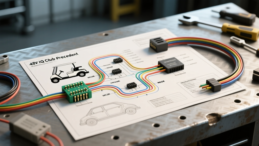
Introduction to the Precedent 48V IQ Electrical Architecture
The Club Car Precedent represented a massive paradigm shift in Personal Transportation Vehicle (PTV) and golf cart engineering. Unlike the older DS models that relied on simple series-wound DC motors and resistor-based speed controls, the Precedent introduced the highly sophisticated 48V IQ System. Understanding the Club Car Precedent wiring diagram requires a fundamental grasp of Separately Excited (SepEx) motor theory, regenerative braking logic, and solid-state power management. This complete walkthrough dissects the primary high-current routing, the On-Board Computer (OBC) integration, and the 16-pin controller logic that keeps the vehicle moving safely and efficiently.
Main Power Routing: Battery Pack to Controller
The heart of the Precedent is its 48-volt battery bank, typically configured with six 8V deep-cycle lead-acid batteries (or four 12V AGM/Lithium equivalents). The main power harness must handle extreme current spikes during initial acceleration and regenerative braking phases.
- Main Positive (B+): Routes from the battery pack positive terminal directly to the heavy-duty stud on the input side of the main solenoid (contactor).
- Solenoid Load Side: The output side of the solenoid connects directly to the B+ terminal on the Curtis motor controller.
- Main Negative (B-): Routes from the battery pack negative terminal directly to the controller's B- terminal, bypassing the solenoid to complete the main high-amperage circuit.
High-Amperage Circuit Specifications & Torque Data
Improper torque on 48V DC terminals is the leading cause of voltage drop, melted lugs, and controller failure. Always adhere to the following specifications when rebuilding the main harness.
| Circuit Segment | OEM Wire Gauge | Recommended Upgrade | Terminal Torque Spec |
|---|---|---|---|
| Battery Interconnects | 4 AWG | 2 AWG | 120 in-lbs (5/16' stud) |
| Main Pos to Solenoid | 4 AWG | 2 AWG | 140 in-lbs (3/8' stud) |
| Solenoid to Controller B+ | 4 AWG | 2 AWG | 140 in-lbs (3/8' stud) |
| Controller B- to Main Neg | 4 AWG | 2 AWG | 140 in-lbs (3/8' stud) |
The Solenoid and the Critical Pre-Charge Circuit
The Precedent utilizes a 48V DC heavy-duty solenoid to act as the main high-current switch. However, connecting a dead 48V battery bank directly to a controller with empty internal capacitors would cause a massive inrush current, instantly welding the solenoid contacts or destroying the controller's internal MOSFETs. To prevent this, the wiring diagram includes a pre-charge circuit bridging the two large solenoid terminals.
This circuit consists of a 470-ohm, 2-watt resistor in series with a 48V diode (oriented to allow current flow toward the controller). When the key is turned on and the Tow/Run switch is engaged, the OBC and logic circuits trigger the small coil terminals on the solenoid. A fraction of a second before the main contacts close, the pre-charge circuit slowly fills the controller capacitors. This extends the life of the contactor and protects the solid-state components. If your cart 'clicks' but won't move, and you measure 48V on the battery side of the solenoid but 0V on the controller side, a blown pre-charge diode is a primary suspect.
MCOR Throttle and 16-Pin Controller Logic
Early Precedent models utilized a Motor Controller Output Regulator (MCOR), while later models transitioned to an inductive throttle sensor. Both serve the same purpose: translating mechanical pedal movement into a variable voltage signal that the controller interprets as torque demand. The MCOR uses a 3-wire harness: 5V Reference, Ground, and Signal Return.
Curtis 1268 SepEx Controller Pinout Breakdown
The IQ system relies heavily on the Curtis 1268 (or similar 1200-series) SepEx controller. Below is a simplified reference for the primary 16-pin logic connector that interfaces with the cart's chassis harness.
| Pin Number | Wire Color (Typical) | Function / Destination | Operating Voltage / State |
|---|---|---|---|
| 1 | Red | Main Contactor Coil (via OBC) | 48V when pedal pressed |
| 2 | Black | Logic Ground | 0V Reference |
| 5 | Green | MCOR Throttle Signal Input | 0.8V (Rest) to 3.2V (Full) |
| 6 | Yellow | 5V Reference to MCOR | 5.0V DC Constant |
| 8 | Blue | Forward Switch Input | 48V in Forward |
| 9 | White | Reverse Switch Input | 48V in Reverse |
| 13 | Orange | Regen / Brake Switch Input | Active during coasting |
Note: Wire colors can vary slightly depending on the exact model year and whether the harness has been replaced. Always verify with a multimeter against the Club Car Official Service Manuals.
SepEx Motor Wiring: Armature vs. Field
Unlike older series-wound motors, the Precedent's SepEx (Separately Excited) motor features isolated armature and field windings. This allows the controller to manipulate the field current independently of the armature current, enabling features like regenerative braking and precise speed limiting.
- Armature Terminals (A1, A2): Connected directly to the controller's main motor outputs. These handle the highest amperage and require 4 AWG or 2 AWG cables.
- Field Terminals (F1, F2): Connected to the controller's field outputs. By reversing the field polarity electronically, the controller changes the cart's direction without needing heavy-duty mechanical reversing contactors.
Regenerative Braking Physics: When you lift off the throttle, the controller actively excites the field windings while the armature is still spinning from the vehicle's momentum. The motor acts as a generator, pushing 48V+ back through the controller to recharge the batteries. This is why Precedent brake pads last significantly longer than those on older gas or series-electric carts.
The On-Board Computer (OBC) Integration
You cannot properly troubleshoot a Precedent wiring diagram without understanding the OBC. The OBC monitors the battery pack voltage and controls the charging relay. It features a 6-pin connector that splices into the main harness. If the OBC detects that the pack voltage has dropped below 38V, it will open the internal relay, preventing the charger from turning on to protect the batteries from deep-discharge sulfation. A common failure mode is a cart that runs fine but refuses to charge; bypassing the OBC relay temporarily will confirm if the computer has locked out the system.
Common Precedent Wiring Failure Modes & Diagnostics
When diagnosing electrical gremlins, follow this expert decision tree based on common field failures documented by technicians and enthusiasts in the Buggies Gone Wild Electric Archive:
- Symptom: Cart is completely dead, no solenoid click.
Check: Tow/Run switch continuity. Key switch 48V output. OBC internal relay. 10A inline fuse on the positive battery post. - Symptom: Solenoid clicks, but cart does not move.
Check: Pre-charge diode/resistor. MCOR signal voltage (must sweep smoothly from 0.8V to 3.2V). Controller high-pedal lockout (HPD) - if the pedal was pressed when the key was turned on, the controller disables drive for safety. - Symptom: Cart moves but lacks top speed or torque.
Check: Voltage drop across the solenoid under load (should be less than 0.5V). Motor brush wear. F1/F2 field winding resistance (should read between 2.0 and 4.0 ohms).
Safety and SAE Compliance for 48V DC Systems
Working on 48V DC systems poses significant arc-flash and shock hazards. According to SAE J1211 standards for Low-Speed Vehicle Electrical Systems, all main battery disconnects and high-current junctions must be shielded and properly insulated. Always place the Tow/Run switch in the 'TOW' position before disconnecting any battery cables or controller logic plugs. This isolates the OBC and prevents voltage spikes from back-feeding into the delicate 5V logic circuits, which can instantly destroy the microprocessor inside the motor controller.