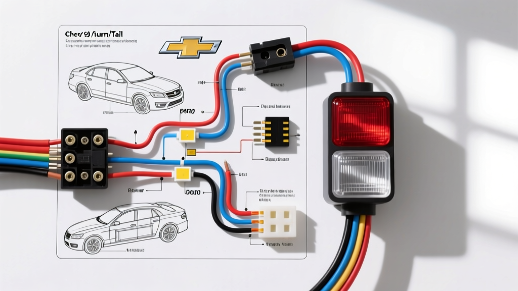
Decoding the Chevy Stop/Turn/Tail Light Wiring Diagram
Whether you are restoring a classic OBS (1988-1998) C/K1500 or upgrading a GMT800 Silverado (1999-2006), understanding the foundational Chevy stop/turn/tail light wiring diagram is critical for any electrical modification project. General Motors utilizes a standardized 4-wire rear lighting architecture that combines the brake and turn signal circuits on a single filament (using 1157 or 3157 dual-filament bulbs), while dedicating a separate circuit for the running/parking lights. When planning an LED conversion, integrating a heavy-duty trailer harness, or wiring a custom camper shell, relying on generic aftermarket kits often leads to Body Control Module (BCM) faults, hyperflashing, or catastrophic backfeed issues.
This technical guide provides the exact OEM wire color codes, AWG specifications, and modification protocols required to safely upgrade your Chevy truck's rear lighting network without triggering the DIC (Driver Information Center) 'Service Trailer Brake' or 'Check Taillights' warnings.
OEM Rear Harness Wire Color Reference & Pinout
The following table outlines the standard GM rear lighting harness parameters. Note that while these colors apply to the vast majority of Chevy trucks from 1988 through the mid-2000s, always verify with a digital multimeter (DMM) at the Rear Junction Block (RJB) or the rear bumper harness before cutting into the loom.
| Wire Color | Function | OEM AWG | Load Profile (Incandescent) | Voltage State |
|---|---|---|---|---|
| Yellow | Left Stop / Turn Signal | 14 AWG | 2.1A (Stop) / 0.6A (Tail) | 12V Pulsed / Static |
| Dark Green | Right Stop / Turn Signal | 14 AWG | 2.1A (Stop) / 0.6A (Tail) | 12V Pulsed / Static |
| Brown | Tail / Parking / Marker | 14 AWG | 0.6A per lamp | 12V Constant (Headlights On) |
| Black / White | Chassis Ground | 12 AWG | N/A | 0V (Continuity to Battery -) |
Modification Project 1: High-Output LED Tail Light Conversion
Upgrading to LED tail light assemblies is one of the most popular Chevy truck modifications, offering faster illumination times (improving rear-end collision safety) and a modern aesthetic. However, LEDs draw a fraction of the current of incandescent bulbs. A standard 1157 incandescent bulb draws approximately 2.1 Amps on the stop/turn filament. A comparable LED array draws between 0.15A and 0.30A.
In GMT800 and newer Chevys, the BCM or Rear Auxiliary Lamp (RAL) module monitors the voltage drop across the circuit. When it detects the low current draw of an LED, it assumes the bulb is blown. This triggers a hyperflash (rapid blinking at 120+ cycles per minute instead of the SAE-mandated 60-120 CPM) and illuminates a dash warning.
Load Resistor Sizing and Thermal Management
To bypass this diagnostic loop without reprogramming the BCM, you must install load resistors to simulate the missing amperage. For Chevy trucks, 50-Watt, 6-Ohm aluminum-housed load resistors are the standard specification.
- Wiring Topology: Resistors must be wired in parallel with the LED, not in series. You will tap the resistor's positive wire into the Yellow (Left) or Dark Green (Right) wire, and the negative wire into the Black/White ground wire.
- Splicing Hardware: Avoid cheap blue plastic T-taps, which fray 14 AWG stranded copper and invite moisture corrosion. Use Posi-Tap connectors or, for a permanent mil-spec fix, strip the OEM wire, solder the resistor pigtail using a Western Union splice, and seal with dual-wall polyolefin heat shrink (3/16 inch, 4:1 shrink ratio with EVA adhesive lining).
- Thermal Dissipation: A 50W resistor under constant braking (e.g., sitting in traffic) will reach surface temperatures exceeding 300°F (150°C). Never zip-tie these resistors to plastic bumper covers, rubber wire looms, or insulated bed liners. They must be bolted directly to the bare steel frame rail or the metal bed crossmember using the included self-tapping screws and a thin layer of thermal paste.
Modification Project 2: Integrating a 4-Pin Trailer Harness
When adding a trailer harness to a Chevy truck not equipped with the factory Z82 towing package, you must tap into the main Chevy stop/turn/tail light wiring diagram. While the factory provides a blunt-cut dummy harness taped up under the rear bumper on many models, hardwiring is often required on base fleet models or older OBS trucks.
Diode Isolation for Custom Campershells and Caps
If your modification includes wiring a camper shell with separate LED brake and turn signal bulbs (a 5-wire or 6-wire setup), tapping directly into the Chevy's combined Yellow and Dark Green wires will cause backfeed. When you hit the brakes, current will flow backward through the turn signal filament and illuminate the opposite side of the truck, or trigger the BCM to cut power to the circuit to protect against a perceived short.
The Fix: Install heavy-duty 35-Amp P-N (Positive-Negative) isolation diodes on the Yellow and Dark Green feed wires before they branch off to the camper shell. This ensures current flows strictly one-way (from truck to shell) and prevents the camper shell's separate brake circuit from backfeeding into the truck's turn signal logic.
Troubleshooting Matrix: Ground & Backfeed Issues
Electrical gremlins in Chevy rear lighting almost always stem from poor grounding or incorrect splicing. Use this decision tree to diagnose common modification failures.
Symptom 1: Tail Lights Illuminate When Brake is Pressed, But No Turn Signal
- Cause: High resistance on the main chassis ground (G402 or G403). Current from the brake filament seeks the path of least resistance, backfeeding through the tail filament and into the opposite side's circuit.
- Diagnostic Step: Perform a voltage drop test across the ground wire and the bare frame. A reading above 0.1V under load indicates a bad ground.
- Fix: Locate the ground ring terminal on the frame rail. Remove the bolt, sand away the factory e-coat/powder coat down to bare metal using 80-grit sandpaper, apply a dab of zinc-rich anti-seize or dielectric grease, and re-torque the M6 ground stud to 80 lb-in (9 Nm).
Symptom 2: Hyperflash Only on One Side After LED Upgrade
- Cause: The load resistor ground wire has a poor crimp or is grounded to a painted surface, preventing the resistor from pulling adequate current to satisfy the BCM.
- Diagnostic Step: Use an infrared thermometer to check the resistor housing while the turn signal is active. If it remains cold, it is not completing the circuit.
- Fix: Cut off the quick-splice terminal. Strip the 14 AWG resistor wire and crimp a closed-barrel, nylon-insulated ring terminal using a Delphi/Hella ratcheting crimp tool. Secure to bare frame metal.
Symptom 3: DIC Displays 'Check Trailer Wiring' When Plugging in a Boat
- Cause: The trailer's incandescent surge exceeds the BCM's 15-Amp circuit limit, or moisture in the trailer's 4-pin plug is bridging the Brown (Tail) and Green (Right Turn) pins.
- Diagnostic Step: Unplug the trailer and test the truck's harness pins with a DMM. If the truck side reads cleanly, the fault is in the trailer plug.
- Fix: Disassemble the trailer-side 4-way plug, clean the copper contacts with electrical contact cleaner, and pack the rear of the connector with marine-grade dielectric grease to prevent capillary water wicking into the Chevy's rear harness.
Authoritative References & Standards
When executing lighting modifications, always adhere to federal and automotive engineering standards to ensure road legality and safety:
- SAE J578 Lighting Color Standards - Governs the exact chromaticity coordinates for automotive amber turn signals and red stop lamps, crucial when selecting aftermarket LED replacements to avoid illegal color tinting.
- GM Upfitter Electrical Body Builder Manuals - The definitive OEM resource for GM truck circuit diagrams, RJB pinouts, and maximum allowable current draw limits for aftermarket accessories.
- Aptiv (Delphi Packard) Connector Specifications - Technical data sheets for Metri-Pack 280 and Weather-Pack sealed connector systems used in GM OEM rear harnesses, including terminal crimp profiles and mating force tolerances.