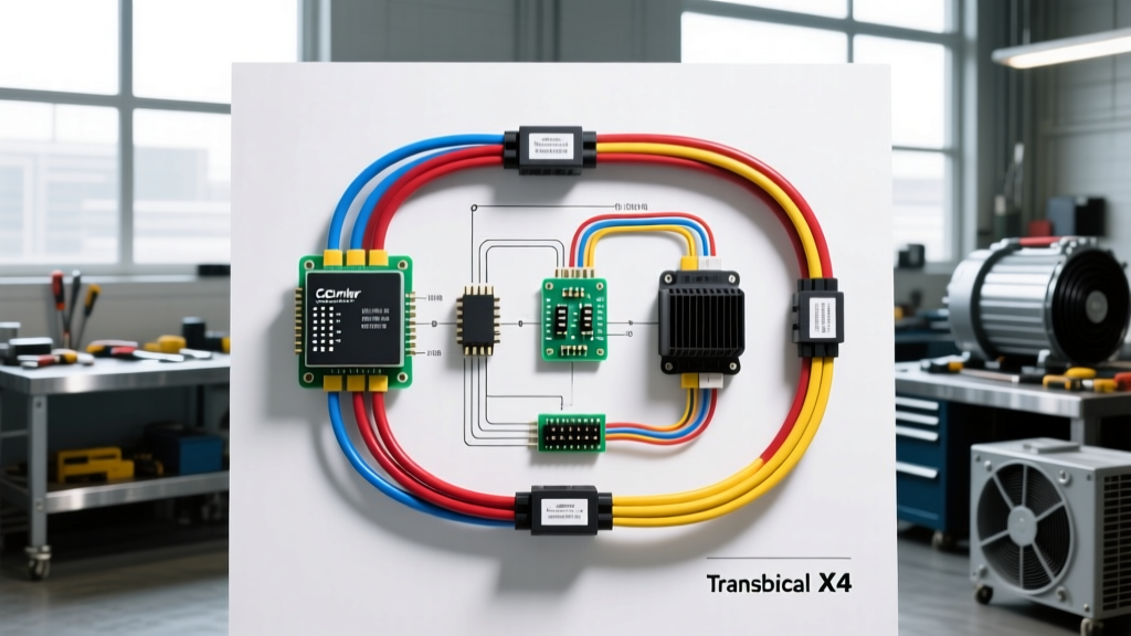
Introduction to Carrier Transicold X4 Electrical Architecture
When diagnosing climate control failures in commercial freight, understanding the carrier wiring diagram for the Transicold X4 series is non-negotiable for advanced heavy-duty technicians. Unlike legacy belt-driven transport refrigeration units (TRUs), the Carrier X4 platform utilizes a revolutionary beltless architecture. The diesel engine directly drives a high-output, brushless 3-phase generator, which in turn supplies power to an electric scroll compressor. This eliminates mechanical belts and tensioners but drastically increases the complexity of the electrical harness, requiring a deep understanding of high-voltage AC routing, electromagnetic interference (EMI) shielding, and multiplexed CAN bus networks.
This advanced technical deep dive dissects the Carrier Transicold X4 wiring schematic, focusing on the MicroLINK 5i Electronic Control Unit (ECU) pinouts, 3-phase generator circuits, sensor networks, and SAE J1939 integration. Whether you are troubleshooting a high-voltage ground fault, a communication dropout, or a thermistor drift, this guide provides the OEM-level specifications required for precise diagnostics.
High-Voltage 3-Phase Generator and Compressor Circuit
The heart of the X4 electrical system is the engine-driven generator. Operating at 1800 RPM in high-speed mode, the stator produces 460V AC 3-phase power. In low-speed mode (1200 RPM), it steps down to 230V AC. The wiring from the generator rectifier assembly to the electric scroll compressor motor requires strict adherence to gauge and routing specifications to prevent voltage drop and EMI cross-talk.
- Wire Gauge: 4 AWG stranded, high-temperature (105°C) copper.
- OEM Color Code: Phase U (Brown), Phase V (Black), Phase W (Gray).
- Grounding: The compressor motor chassis must be bonded to the trailer frame using a minimum 8 AWG green/yellow bonding strap. Torque the grounding lug to 15 lb-ft to ensure a low-resistance path for fault currents.
- Routing & Shielding: The 460V AC lines must be routed in a dedicated, flexible metallic conduit. They must never share a conduit or wire tie with the 12V DC CAN bus or thermistor wiring. Failure to separate these circuits induces high-frequency noise onto the data lines, resulting in MicroLINK 5i ECU reboots and active fault codes related to network loss.
Safety Warning: Always perform Lockout/Tagout (LOTO) procedures and verify zero energy state with a CAT III rated multimeter before probing the generator terminal block. The generator produces lethal voltage whenever the engine is cranking or running, even if the ECU is powered down.
MicroLINK 5i ECU Main Harness Pinout Diagram
The MicroLINK 5i controller acts as the brain of the TRU, managing engine governor signals, compressor contactors, defrost cycles, and telematics. The main power and I/O harness utilizes a heavy-duty, sealed Amphenol-style connector. Below is the critical pinout reference for the primary 24-pin power and data interface.
| Pin | Function | Wire Color | AWG | Technical Notes |
|---|---|---|---|---|
| 1 | +12VDC Battery Direct | Red | 10 | Fused at 30A. Powers ECU memory and RTC. |
| 2 | Chassis Ground | Black | 10 | Must measure < 0.05 ohms to battery negative. |
| 3 | Ignition / Run Signal | White | 16 | Switched 12V from tractor 7-way pin 8 (aux). |
| 14 | J1939 CAN High | Yellow | 18 | Twisted pair. 120-ohm internal termination. |
| 15 | J1939 CAN Low | Green | 18 | Twisted pair. Shield grounded at ECU only. |
| 18 | Compressor Contactor Coil (+) | Orange | 14 | Switched ground via ECU driver transistor. |
| 22 | Evaporator Thermistor Sig | Blue | 20 | Shielded twisted pair. 10k NTC at 25°C. |
| 23 | Thermistor Common | White/Blue | 20 | Reference voltage return for sensor network. |
For comprehensive connector mappings and torque specifications for the ECU mounting plate, technicians should consult the official Carrier Transicold Service Documentation portal.
Sensor Networks: Thermistors and Shielding Practices
Accurate temperature regulation relies on the integrity of the Return Air and Supply Air thermistors. The X4 system uses 10,000 Ohm Negative Temperature Coefficient (NTC) thermistors. As the temperature drops, resistance increases. At 77°F (25°C), the resistance should read exactly 10kΩ. At 32°F (0°C), expect a reading of approximately 27.2kΩ.
The wiring for these sensors is highly susceptible to electromagnetic interference due to the high-voltage environment of the TRU. Carrier specifies 20 AWG shielded twisted pair (STP) wire for all thermistor runs. Critical Installation Rule: The foil shield and drain wire must be terminated and grounded only at the MicroLINK 5i ECU connector shell. Grounding the shield at the sensor end (inside the trailer box) creates a ground loop, allowing stray AC currents from the trailer chassis to induce voltage offsets on the signal wire, causing the ECU to read erratic temperatures and initiate false defrost cycles.
J1939 CAN Bus Integration and Telematics
Modern fleet management requires the TRU to communicate with the tractor’s Engine Control Module (ECM) and third-party telematics devices. The Carrier X4 utilizes the SAE J1939 Standard for heavy-duty vehicle networks. The CAN bus operates at 250 kbps.
When integrating the X4 into a new trailer harness, adherence to the ATA Technology & Maintenance Council (TMC) RP-158 guidelines for trailer wiring is essential. The J1939 backbone must feature exactly two 120-ohm termination resistors—one at each physical end of the network. The MicroLINK 5i ECU contains one internal 120-ohm resistor. If the ECU is the last node on the drop, the opposing end of the trailer harness must have a physical terminating resistor installed.
CAN Bus Diagnostics:
- Resistance Test (Power OFF): Measure between Pin 14 (CAN H) and Pin 15 (CAN L). You must read exactly 60 ohms. A reading of 120 ohms indicates a missing terminator; a reading near 0 ohms indicates a short.
- Voltage Test (Power ON, Idle): CAN H should rest at approximately 2.5V to 2.6V, and CAN L should rest at 2.4V to 2.5V. During active transmission, an oscilloscope will show CAN H spiking to ~3.5V and CAN L dropping to ~1.5V.
Gas Defrost Solenoid and Heating Circuits
The X4 utilizes a hot-gas defrost system, bypassing high-pressure, high-temperature refrigerant vapor directly into the evaporator coil to melt ice accumulation. This is controlled by the gas defrost solenoid valve. The solenoid coil operates on 12V DC and draws an inrush current of approximately 1.5A, settling to a holding current of 0.8A. The OEM wire color for the solenoid positive feed is 14 AWG Orange, protected by a 5A mini-blade fuse located on the MicroLINK 5i main board. If the fuse blows repeatedly, do not simply upsize the fuse. Inspect the solenoid coil for internal shorts or check the wiring harness where it passes through the trailer bulkhead, a common pinch point that leads to insulation failure and chassis grounding.
Advanced Troubleshooting: Voltage Drops and Ground Faults
When a Carrier X4 unit fails to start or logs active 'Low Voltage' or 'ECU Reset' faults, the issue rarely lies within the MicroLINK board itself. Instead, it is almost always a voltage drop on the primary 12V DC supply or ground circuit. Because the electric scroll compressor contactor and the fuel solenoid draw significant amperage during startup, a corroded battery cable or a loose chassis ground will cause the ECU supply voltage to momentarily dip below 9.0V, triggering a brownout reset.
Perform a Loaded Voltage Drop Test:
- Set your multimeter to DC Volts.
- Place the red probe on the positive battery post and the black probe on Pin 1 of the ECU harness (back-probed).
- Crank the TRU engine or force the compressor contactor to engage via the keypad.
- A voltage drop greater than 0.5V on the positive side, or greater than 0.2V on the ground side (Pin 2 to battery negative), indicates excessive resistance requiring terminal cleaning, crimp replacement, or wire gauge upgrades.
By mastering the intricacies of the carrier wiring diagram, from 460V AC generator routing to shielded CAN bus topologies, technicians can drastically reduce diagnostic time and ensure the cold-chain integrity of modern commercial freight operations.