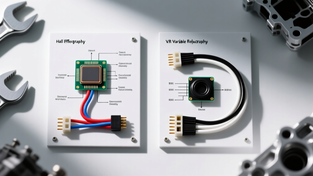
Understanding the Cam Sensor Wiring Diagram: Sensor Topologies
When diagnosing a P0340 (Camshaft Position Sensor Circuit) code or performing an aftermarket ECU swap, interpreting the cam sensor wiring diagram is the critical first step. The camshaft position sensor (CMP) dictates sequential fuel injection and variable valve timing (VVT) phasing. However, not all CMP sensors operate on the same electrical principles. Selecting the correct replacement pigtail, connector, and wiring harness requires a deep understanding of the three primary sensor topologies used in modern automotive applications: Variable Reluctance (VR), Hall Effect, and Optical.
According to Motor Service International (MSI), misidentifying the sensor type and applying the wrong wiring configuration is one of the leading causes of ECU damage and persistent no-start conditions. A VR sensor generates its own AC voltage signal and requires only two wires, while a Hall Effect sensor requires an external 5V or 12V reference, a ground, and a signal wire. Swapping these harnesses will result in immediate circuit failure.
OEM Cam Sensor Wiring Diagram Pinouts: GM LS vs. Ford Coyote
To illustrate the differences in harness selection, we must examine the specific pinouts and wire color codes of two of the most popular engines in the aftermarket and repair spaces: the GM LS V8 (Hall Effect) and the Ford 5.0L Coyote V8 (Variable Reluctance).
GM LS Gen III/IV (Hall Effect CMP)
The GM LS platform utilizes a 3-wire Hall Effect sensor mounted on the front timing cover. The cam sensor wiring diagram for this application relies on a Delphi Metri-Pack 150 series 3-way connector.
- Pin A (12V Reference): Pink or Red/White wire, 18 AWG. Supplies switched ignition voltage from the PCM.
- Pin B (CMP Signal): Brown or Blue wire, 20 AWG. Carries the 5V/12V DC square wave signal back to the ECU.
- Pin C (Low Reference/Ground): Black or Purple/White wire, 18 AWG. Dedicated PCM sensor ground.
Ford 5.0L Coyote (Variable Reluctance CMP)
Ford’s Coyote engine uses a 2-wire Variable Reluctance (Magnetic) sensor. Because VR sensors generate an alternating current (AC) sine wave as the reluctor wheel passes the magnetic core, they do not require an external power supply. The connector is typically a Bosch/Jetronic Mini-Timer or Ford-specific 2-way sealed housing.
- Pin 1 (Signal +): Gray/Orange wire, 20 AWG.
- Pin 2 (Signal -): Gray/Brown wire, 20 AWG.
As detailed in the AutoShop101 Engine Sensor Diagnostics manual, VR sensors are highly susceptible to electromagnetic interference (EMI). Therefore, the cam sensor wiring diagram for these applications mandates that the two signal wires be routed as a twisted pair to cancel out induced noise from adjacent ignition coil harnesses.
Product Selection Guide: Choosing the Right Pigtail and Harness
When replacing a damaged CMP connector or building a custom engine harness, the quality of the pigtail and wire insulation is just as important as the pinout. The aftermarket offers various cam sensor wiring harness kits, but they are not created equal.
Wire Insulation: PVC vs. PTFE (Tefzel)
Standard OEM replacement pigtails often use Cross-Linked Polyethylene (XLPE) or Polyvinyl Chloride (PVC) insulation. While adequate for stock engine bays, PVC becomes brittle over time when exposed to sustained header heat and oil vapors. For high-performance applications, engine swaps, or turbocharged setups, you must select harnesses utilizing PTFE (Polytetrafluoroethylene) insulation, commonly known by the DuPont trademark Tefzel.
PTFE wire (meeting MIL-W-22759/16 military specifications) is rated for continuous operation at 200°C (392°F), is highly resistant to automotive fluids, and allows for a thinner insulation wall. This thinner wall reduces the overall harness diameter and weight while increasing flexibility, making it vastly superior for routing through tight firewall grommets and behind timing covers.
Connector Terminals and Crimping Standards
Never solder wires directly to the sensor pigtail terminals. Solder creates a rigid joint that will fatigue and crack under the high-frequency vibration inherent to the engine block. Instead, select pigtails that feature open-barrel copper terminals designed for open-barrel crimping. Adhering to USCAR-21 crimping standards ensures a gas-tight mechanical connection that will outlast the vehicle. Ensure your crimping tool matches the specific terminal series (e.g., Delphi Metri-Pack 150, Bosch Superseal 1.5, or TE Connectivity AMP) to avoid improper bellmouth formation.
Harness & Wiring Specification Comparison Chart
| Feature | Variable Reluctance (VR) | Hall Effect | Optical |
|---|---|---|---|
| Wire Count | 2 Wires | 3 Wires | 3 to 4 Wires |
| Signal Type | AC Sine Wave | DC Square Wave | DC Square Wave (Digital) |
| Power Requirement | None (Self-Generating) | 5V, 8V, or 12V Reference | 5V or 12V Reference |
| Ideal Wire Gauge | 20 AWG to 22 AWG | 18 AWG (Power), 20 AWG (Signal) | 20 AWG (All) |
| Shielding Required? | Yes (Twisted Pair Mandatory) | Recommended for Signal Wire | Mandatory |
| Common Connector | Bosch Jetronic / Mini-Timer | Delphi Metri-Pack 150 / 280 | Proprietary / Sealed Circular |
Critical Wiring Practices: Shielding and EMI Mitigation
The most common failure mode in aftermarket cam sensor wiring is not a broken wire, but signal degradation caused by Electromagnetic Interference (EMI). Modern ignition systems, particularly Capacitive Discharge (CD) ignition boxes and high-output coil-near-plug (CNP) setups, generate massive amounts of RF noise.
If your cam sensor wiring diagram routes the CMP signal wire parallel to the main ignition coil power feed, the ECU may read the ignition spike as a false camshaft tooth. This results in erratic VVT solenoid operation, misfires, or the engine going into limp mode. To mitigate this:
- Cross at 90-Degree Angles: If the CMP harness must cross an ignition harness, ensure they intersect at a strict 90-degree angle to minimize inductive coupling.
- Utilize Shielded Cable: For Hall Effect sensors, use a shielded 3-conductor cable for the pigtail extension. The drain wire (shield) must be grounded only at the ECU end, never at the sensor end. Grounding both ends creates a ground loop, which will actively introduce alternator whine and noise into the signal circuit.
- Maintain Air Gap Specs: While not strictly a wiring issue, remember that the physical installation torque of the sensor (typically 8-10 Nm or 71-89 lb-in) dictates the air gap. An improper air gap alters the amplitude of the VR sine wave or the duty cycle of the Hall square wave, which the ECU may interpret as a wiring fault.
Troubleshooting Signal Degradation with an Oscilloscope
Multimeters are insufficient for diagnosing cam sensor wiring issues. A digital multimeter (DMM) averages voltage over time and cannot capture the microsecond transitions of a CMP signal. You must use a digital storage oscilloscope (DSO).
When probing the harness pigtail back-probes, a healthy VR sensor will show an AC sine wave that increases in both frequency and amplitude (voltage) as engine RPM rises. A healthy Hall Effect sensor will show a crisp, flat-topped DC square wave transitioning cleanly between 0V and the reference voltage (e.g., 5V or 12V). If the square wave shows rounded corners, excessive ringing, or fails to pull all the way down to 0V, you likely have excessive resistance in the ground circuit, a corroded terminal in the Metri-Pack connector, or a failing pull-up resistor inside the ECU. Always consult the specific Delphi Automotive Connector Systems documentation to verify terminal retention force and mating specifications when signal integrity is compromised.
Summary: Selecting Your Harness
Whether you are repairing a melted OEM harness or building a standalone mil-spec engine loom, matching the cam sensor wiring diagram to the correct physical components is non-negotiable. Verify your sensor topology (VR vs. Hall), select the appropriate wire gauge (18 AWG for power, 20 AWG for signal), utilize PTFE insulation for high-heat zones, and adhere strictly to open-barrel crimping standards. By treating the sensor harness as a high-frequency data network rather than a simple power cable, you ensure reliable engine synchronization and optimal performance.