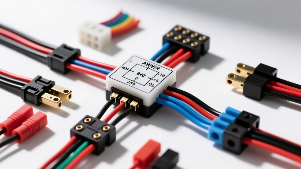
Introduction to Automotive Timer Switch Applications
In modern vehicle customization and electrical system upgrades, managing accessory power is paramount. Whether you are wiring an off-road light bar with an auto-shutoff feature to prevent battery drain, installing a glow plug delay relay for a diesel engine swap, or configuring a winch solenoid safety cutoff, finding the correct wiring diagram for timer switch integration is critical. Unlike standard 5-pin Bosch-style relays that require constant manual or ignition-switched input, timer switches introduce a temporal logic layer to your vehicle's electrical harness. This ensures high-draw accessories do not parasitically drain the starter battery when the vehicle is parked. This guide compares the three primary automotive timer switch technologies, outlines strict wire gauge requirements, and provides a comprehensive, heavy-duty 8-pin solid-state wiring diagram for timer switch installations.
Product Comparison: Selecting the Right Timer Module
Before cutting into your vehicle's harness, you must select a timer module capable of surviving the harsh automotive environment. The 12V automotive electrical system is plagued by voltage spikes, load dump transients (up to 40V), and extreme under-hood temperatures. Here is a comparison of the three most common timer switch architectures used in automotive applications.
| Timer Technology | Timing Accuracy | Max Continuous Load | Trigger Type | Best Automotive Application |
|---|---|---|---|---|
| Analog RC Delay | Low (±20% drift) | 10A (Internal) | 12V+ Rising Edge | Dome light fade-out, simple HVAC blower delay |
| Thermal Bimetallic | Very Low (Temp dependent) | 15A (Internal) | Current Flow | Vintage wiper delay circuits, thermal flashers |
| Solid-State Digital (Microcontroller) | High (±1%) | 30A+ (MOSFET driven) | 12V+ or Ground | Off-road lighting auto-shutoff, winch solenoid safety, fuel pump priming |
For any modern auxiliary wiring project, the Solid-State Digital Timer is the only recommended choice. Analog RC circuits suffer from severe timing drift as under-hood temperatures fluctuate, and thermal switches introduce dangerous voltage drops. Solid-state modules utilize internal MOSFETs to handle heavy loads without mechanical arcing, provided they are wired with appropriate flyback diodes and transient voltage suppression (TVS).
Universal Wiring Diagram for Timer Switch (8-Pin Solid-State)
The following wiring diagram for timer switch configurations is based on the industry-standard 8-pin sealed solid-state timer relay (commonly housed in a TE Connectivity or Deutsch DT-style sealed connector). This specific module features an "Off-Delay" logic, meaning the load remains powered as long as the trigger is active, and then counts down once the trigger is removed.
Pinout Configuration and SAE Wire Codes
When building your custom harness, always adhere to SAE J1128 standards for low-tension primary cable, specifically utilizing Cross-Linked Polyethylene (XLPE) insulation for under-hood routing to resist heat and chemical degradation.
- Pin 1: 12V+ Constant Battery Feed
Wire Color: Red | Gauge: 10 AWG | Route directly to the positive battery terminal via a fused distribution block. Do not use ignition-switched power here, or the timer will reset when the key is turned off. - Pin 2: Chassis Ground
Wire Color: Black | Gauge: 10 AWG | Terminate using a ring terminal on a clean, bare-metal chassis point. Use a star washer to bite through paint and prevent ground loop resistance. - Pin 3: Trigger Input (Switch)
Wire Color: Blue | Gauge: 16 AWG | Connect to your manual toggle switch or ignition-run circuit. This pin requires a minimum of 6V to register a "High" logic state. - Pin 4: Load Output (Accessory)
Wire Color: Yellow | Gauge: 10 AWG | Connect to the positive feed of your accessory (e.g., light bar relay coil, winch contactor). Capable of sourcing up to 30A continuously. - Pin 5: Programming / Time Adjust
Wire Color: White | Gauge: 18 AWG | Connect to a momentary push-button or a variable resistor (potentiometer) to adjust the delay time from 10 seconds to 10 minutes. - Pin 6: Override / Instant Cancel
Wire Color: Green | Gauge: 18 AWG | Grounding this pin instantly kills the output, bypassing the countdown timer. Useful for emergency shutoffs. - Pin 7: Status LED Indicator
Wire Color: Violet | Gauge: 20 AWG | Connect to a dashboard LED (with a 470-ohm resistor) to indicate when the timer is actively counting down. - Pin 8: Sensor / Ground Reference
Wire Color: Brown | Gauge: 18 AWG | Provides a dedicated 5V reference ground for the programming potentiometer on Pin 5.
Wire Gauge Sizing and Voltage Drop Calculations
A common mistake when executing a wiring diagram for timer switch setups is undersizing the constant power and ground wires. While the trigger circuit (Pin 3) only draws milliamps, the main power circuit (Pins 1, 2, and 4) must handle the full inrush and continuous current of the load. According to Littelfuse automotive relay guidelines, a 30A continuous load requires a minimum of 10 AWG wire for runs up to 15 feet to maintain a voltage drop below 3%.
Use the following voltage drop formula to verify your harness design:
VD = (2 × L × I × R) / 1000
- VD = Voltage Drop (Volts)
- L = One-way wire length in feet
- I = Current draw in Amps
- R = Wire resistance per 1000 ft (10 AWG Copper ≈ 1.0 ohm)
For a 20-foot total run (10 ft to the accessory, 10 ft to ground) pulling 25A through 10 AWG wire: VD = (2 × 10 × 25 × 1.0) / 1000 = 0.5 Volts. This is well within the acceptable 3% threshold (0.36V on a 12V system, though 0.5V is generally acceptable for auxiliary lighting). If your run exceeds 15 feet, step up to 8 AWG to prevent the timer's internal low-voltage lockout (LVLO) circuitry from prematurely terminating the countdown.
Real-World Troubleshooting and Failure Modes
Even with a perfect wiring diagram for timer switch integration, the harsh realities of vehicle electrics can cause erratic behavior. Below is a diagnostic decision tree for common solid-state timer failures.
Symptom: Timer Resets or Output Drops During Engine Cranking
Cause: When the starter motor engages, system voltage can plummet to 7V–9V. Most digital timer modules feature an internal Low-Voltage Reset (LVR) that reboots the microcontroller if VCC drops below 9V, instantly killing the load.
Fix: Install a 1000µF, 25V electrolytic capacitor across Pin 1 (12V+) and Pin 2 (Ground) at the timer connector. This capacitor will act as a localized buffer, supplying the microcontroller with enough reserve current to ride out the 2-second cranking voltage sag without resetting the logic state.
Symptom: Timer Module Melts or Fails Instantly Upon Load Shutoff
Cause: Inductive kickback (Back-EMF). If Pin 4 is driving an inductive load like a winch solenoid coil or a standard mechanical relay, the collapsing magnetic field generates a voltage spike exceeding 100V when the internal MOSFET switches off. This spike punches through the solid-state silicon.
Fix: You must install a flyback diode (e.g., 1N5408, rated for 3A/1000V) in reverse bias across the load's terminals. The cathode (silver stripe) must point toward the 12V+ side. This provides a safe recirculation path for the inductive spike, protecting the timer's internal circuitry.
Symptom: Alternator Whine in Audio System When Timer is Active
Cause: High-frequency PWM switching inside the solid-state timer is bleeding noise back into the vehicle's DC bus, which is then picked up by the head unit's amplifier via a shared ground.
Fix: Relocate the timer's ground (Pin 2) to a dedicated grounding bus bar. Do not share a ground stud with audio equipment or ECU sensors. Additionally, install a ferrite bead choke on the Red 12V+ feed wire within 2 inches of Pin 1 to suppress high-frequency EMI radiation.
Conclusion
Mastering the wiring diagram for timer switch applications elevates your vehicle's electrical system from a basic harness to a smart, protected network. By selecting solid-state digital modules, adhering to SAE J1128 wire specifications, and implementing proper flyback diode protection, you ensure your auxiliary accessories operate reliably in the most extreme off-road and under-hood environments. Always verify your voltage drop calculations and use sealed connectors to guarantee long-term corrosion resistance.