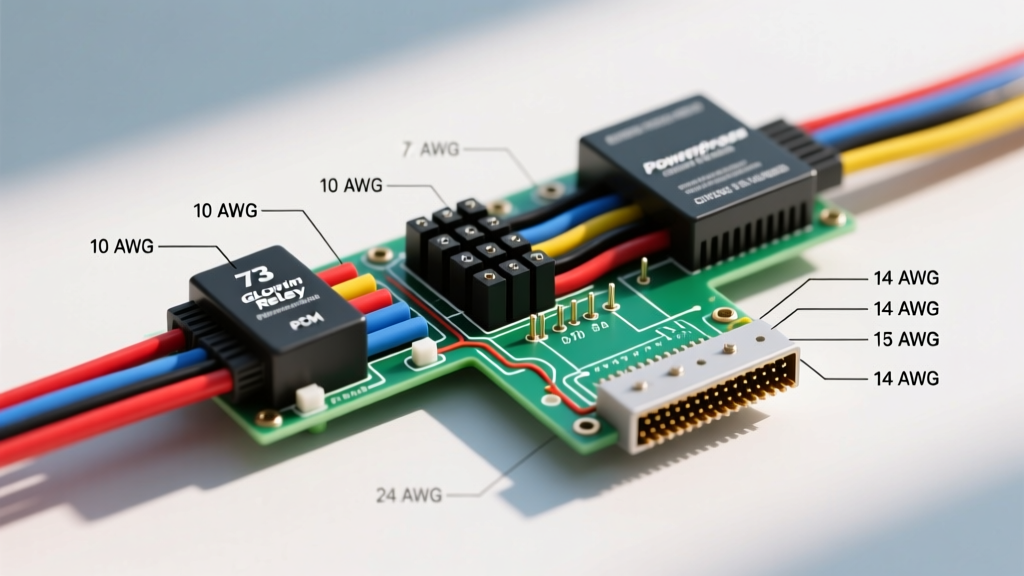
Introduction to the 7.3L Powerstroke Glow Plug System
The Ford 7.3L Powerstroke diesel engine (1994-2003) relies on a high-amperage glow plug system to ensure reliable cold-weather starting. At the heart of this system is the Glow Plug Relay (GPR), a heavy-duty solenoid mounted on the driver-side fender well or engine valley, depending on the specific model year. Understanding the wiring diagram for glow plug relay 7.3 applications is critical for diagnosing hard-start conditions, no-start scenarios in cold weather, and parasitic battery drains. This complete wiring walkthrough breaks down the OEM harness routing, wire color codes, AWG specifications, and Powertrain Control Module (PCM) logic required to accurately diagnose and repair the circuit.
Complete Wiring Diagram Walkthrough: Terminal Breakdown
The standard 7.3L GPR is a four-terminal, normally-open solenoid. It utilizes two large threaded posts for the high-amperage load circuit and two smaller spade or ring terminals for the low-amperage control circuit. When the PCM commands the relay closed, it bridges the two large posts, sending battery voltage directly to the glow plug bus bars located under the valve covers.
GPR Terminal Specifications and Wire Colors
Below is the definitive reference chart for the Super Duty (1999-2003) and late OBS (1997-1998) 7.3L Powerstroke glow plug relay wiring. Note that early OBS models (1994-1996) may feature slight variations in harness jacket colors, but the functional routing remains identical.
| Terminal | Function | OEM Wire Color (Typical) | AWG Size | Voltage State (Key OFF) | Voltage State (Key ON, Cold) |
|---|---|---|---|---|---|
| Large Post A (B+) | Constant Battery Feed | Red (or Black/Light Green OBS) | 8 AWG | 12.0V - 12.6V | 12.0V - 12.6V |
| Large Post B (Load) | Glow Plug Bus Feed | Black/Orange Stripe | 8 AWG / 10 AWG | 0.0V | 11.5V - 12.2V |
| Small Term I (Ign) | Ignition Switch Feed | Red/Light Green Stripe | 16 AWG | 0.0V | 12.0V - 12.6V |
| Small Term S (Gnd) | PCM Switched Ground | Yellow/Black Stripe | 18 AWG | Floating / Open | Ground (< 0.1V) |
The PCM Control Circuit: How the Relay is Triggered
The glow plug relay is not simply triggered by the ignition key; it is managed by the PCM based on specific environmental and engine parameters. The PCM monitors the Engine Oil Temperature (EOT) sensor and the Barometric Pressure (BARO) sensor. According to Ford Motorcraft PC/ED diagnostics, if the EOT is below approximately 130°F (54°C) and the barometric pressure indicates an altitude where cold-start enrichment is required, the PCM will internally ground the 'S' terminal.
This ground path completes the control circuit, energizing the solenoid coil. The coil draws roughly 1.5 to 2.0 amps, creating the magnetic field necessary to pull the heavy copper contacts together. Once closed, the relay passes the massive inrush current required by the eight glow plugs—often exceeding 190 amps for the first few seconds before dropping to a steady state of roughly 110 amps as the plug resistance increases with heat.
Wait-To-Start (WTS) Light vs. Actual Relay Cycle
A common misconception among 7.3L owners is that the glow plugs deactivate when the dash 'Wait-To-Start' light turns off. The wiring diagram reveals that the WTS light is on a separate PCM-controlled ground circuit. The PCM will extinguish the WTS light after a calculated time (usually 5 to 15 seconds), but it will continue to hold the GPR ground circuit active for up to 120 seconds post-start to reduce white smoke and stabilize idle. Diagnosing the system requires monitoring the actual relay posts, not just the dash indicator.
Harness Routing and the UVCH Bottleneck
Tracing the wiring diagram for glow plug relay 7.3 systems requires following the Black/Orange load wire from the relay's large 'B' post. This wire routes down the driver-side valve cover, splitting at a Y-harness to feed both the driver and passenger side glow plug bus bars. The current must pass through the 42-pin main engine connector and, critically, the Under Valve Cover Harness (UVCH) connectors.
The UVCH connectors are a notorious failure point in the 7.3L wiring diagram. The glow plug pins inside these connectors carry massive current in a high-heat, high-vibration environment. Over time, the female terminals lose their tension, leading to micro-arcing, localized melting, and severe voltage drop. If your GPR is outputting 12.0V on the large 'B' post, but the glow plugs are only receiving 9.5V, the wiring diagram points directly to a degraded UVCH connector or a corroded glow plug bus bar stud nut. Many technicians perform the '50-cent mod' (adding a retaining clip to the UVCH connector) or bypass the connector entirely with soldered pigtails to ensure maximum current delivery.
Step-by-Step Multimeter Diagnostics
To properly validate the wiring diagram and isolate faults, perform the following multimeter tests. Ensure the engine is completely cold (below 100°F) so the PCM will command the relay ON.
Test 1: Constant Battery Feed Verification
- Set your Digital Multimeter (DMM) to DC Volts.
- Place the black probe on the engine block (clean ground) and the red probe on the large 'A' post.
- Expected reading: Within 0.2V of battery resting voltage (e.g., 12.4V).
- Failure Mode: If voltage is low or zero, check the 175-amp Mega Fuse located in the driver-side fender well power distribution box and inspect the 8 AWG Red wire for corrosion.
Test 2: Voltage Drop Across the Relay Contacts
This is the most critical test for evaluating the internal health of the GPR solenoid.
- Turn the ignition key to the ON position (do not crank).
- Place the red DMM probe on the large 'A' post (Battery Feed) and the black probe on the large 'B' post (Load Feed).
- Expected reading: Less than 0.30V DC.
- Failure Mode: A reading of 0.5V to 2.0V+ indicates severely pitted internal copper contacts. The relay is passing some current, but the voltage drop is starving the glow plugs of the amperage needed to reach 2,000°F. Replace the relay immediately.
Test 3: PCM Ground Signal Verification
- Use a standard 12V test light (not an LED, as you need to verify the circuit can handle a slight load).
- Clip the test light to the large 'A' post (Constant 12V).
- Probe the small 'S' terminal (PCM Ground) with the tip of the test light.
- Turn the key ON. The test light should illuminate brightly, indicating the PCM has successfully provided the ground path.
- Failure Mode: If the light does not illuminate, check the Yellow/Black 18 AWG wire for breaks, or verify the EOT sensor resistance. If the EOT sensor reads out of spec (indicating a hot engine to the PCM), the PCM will inhibit the ground signal.
Common Failure Modes and Heavy-Duty Upgrades
The OEM Ford glow plug relays are notorious for premature failure. The internal contacts are simply not rated for the sustained 190-amp inrush current generated by eight Beru-style 7.3L glow plugs. Over time, the arcing pits the contacts, increasing resistance and generating immense heat. It is common to find the nuts on the large posts melted or the bakelite casing cracked.
The Expert Upgrade: When replacing the relay, bypass the standard OEM replacement and install a heavy-duty industrial solenoid, such as the White Rodgers 586-902 or the Stancor 586-102. These units feature massive tungsten-alloy contacts designed for continuous duty in marine and heavy industrial applications, effectively eliminating the pitting issue. When installing the new relay, use a torque wrench to tighten the large post nuts to exactly 45-60 in-lbs. Over-torquing will strip the fine threads or crack the internal ceramic insulator, leading to an immediate short-to-ground.
Furthermore, always inspect the ring terminals on the 8 AWG Black/Orange wire. The high current causes thermal cycling, which can anneal the copper and loosen the crimp. Cut back the wire, strip it fresh, and use a closed-end, heat-shrink adhesive ring terminal (rated for 8 AWG) to ensure a permanent, moisture-proof connection. For comprehensive wire gauge and insulation standards, refer to the SAE J1128 Low Tension Primary Cable specifications, which dictate the thermal limits for automotive harnesses in high-heat engine bays.
Summary
Mastering the wiring diagram for glow plug relay 7.3 Powerstroke engines requires looking beyond the relay itself. A proper diagnosis encompasses the 8 AWG feed cables, the PCM's EOT-driven ground logic, and the integrity of the under-valve-cover harness connectors. By utilizing voltage-drop testing rather than simple continuity checks, and by upgrading to industrial-grade solenoids, you can ensure your 7.3L starts flawlessly in the harshest winter conditions.
For further community-driven wiring schematics and UVCH bypass tutorials, veteran diesel technicians frequently reference the archival guides at Guzzle's 7.3 PSD, which remains a cornerstone resource for 7.3L electrical diagnostics.