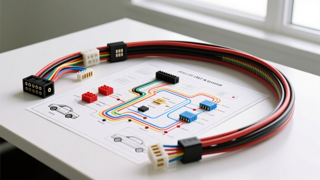
The 1957 Chevy 12-Volt Paradigm Shift
The 1957 Chevrolet (Bel Air, 210, and 150 series) marked a monumental transition in General Motors engineering: the shift from a 6-volt to a 12-volt electrical system. When referencing a 57 Chevy wiring diagram, technicians must account for this 12V architecture, which utilizes specific resistance wires, heavy-duty thermal breakers, and Delco-Remy 12V generators. Unlike modern vehicles with multiplexed CAN-bus networks, the Tri-Five Chevy relies on a straightforward, analog point-to-point copper wiring harness. However, decades of heat cycling, vibration, and aftermarket modifications (such as 1-wire alternator swaps and halogen lighting upgrades) introduce unique failure modes. This guide provides a step-by-step troubleshooting flow based on OEM schematics and real-world diagnostic sequences for the 1957 Chevrolet chassis.
Troubleshooting Flow: Ignition & Starting Circuit Failures
The 1957 ignition circuit routes 12V from the battery to the starter solenoid, with a secondary feed through the ignition switch to the coil. A common failure mode is a 'cranks-but-no-spark' condition, often caused by a bypassed or degraded ballast resistance wire.
Step 1: Verify Starter Solenoid and Battery Feed
Begin at the starter solenoid mounted on the Delco-Remy starter motor. The main battery feed should be a minimum of 10 AWG (often upgraded to 4 AWG red wire). Using a digital multimeter (DMM), measure voltage between the large battery terminal on the solenoid and a clean engine block ground. You must see a minimum of 11.8V with the ignition off. If voltage is below 11.5V, perform a voltage drop test across the positive battery cable and the engine ground strap. Corrosion at the firewall ground strap is a notorious issue on '57 models.
Step 2: Trace the Ignition Switch to Coil Feed
If the engine cranks but lacks spark, move to the ignition switch on the dashboard. The switch receives 12V via a 12 AWG red wire from the starter solenoid's 'BAT' terminal. When the key is turned to 'IGN', power exits the switch via a 14 AWG pink or red wire heading toward the firewall.
- Test Point A (Ignition Switch Output): Probe the IGN terminal on the back of the switch with the key in the 'ON' position. Expected: 12V.
- Test Point B (Coil Positive Terminal): Probe the positive terminal on the ignition coil. Expected: 7V to 9V.
Diagnostic Decision: If you read 12V at the coil positive terminal, the OEM resistance wire has been replaced with standard copper wire. While this provides a hotter spark, it will rapidly burn out the breaker points inside the distributor. According to the Classic Industries Tri-Five Assembly Manual, the OEM harness utilized a specialized Nichrome resistance wire (often identifiable by its stiff, cloth-wrapped texture) to drop the voltage from 12V to approximately 8V at the coil. If the resistance wire is broken, you will read 0V at the coil. Replace it with a dedicated 1.5-ohm ceramic ballast resistor wired in series with a standard 14 AWG copper feed.
Troubleshooting Flow: Headlight & Floor Dimmer Diagnostics
The lighting circuit on the 1957 Chevy is protected by an internal thermal circuit breaker located inside the headlight switch itself. When owners upgrade to modern halogen or LED sealed beams without checking the draw, this breaker frequently cycles or fails entirely.
| Circuit Segment | OEM Wire Color | AWG Size | Function & Routing |
|---|---|---|---|
| Battery to Headlight Switch | Red | 12 AWG | Main 12V feed from fuse box / ammeter |
| Headlight Switch to Dimmer | Red | 14 AWG | Switched 12V feed to floorboard dimmer |
| Dimmer to High Beam | Green | 14 AWG | High beam indicator and headlamp feed |
| Dimmer to Low Beam | Tan | 14 AWG | Low beam headlamp feed |
| Parking Lights | Brown | 16 AWG | Front parking lamp feed (first switch detent) |
Step 1: The Headlight Switch Thermal Breaker Test
Symptom: Headlights turn on, but shut off after 30 seconds, then cycle back on repeatedly.
Diagnosis: The thermal breaker inside the dash switch is tripping due to an over-current condition. Standard 1957 sealed beams draw roughly 4.5 amps each on low beam. If the previous owner installed high-wattage halogen bulbs drawing 8+ amps, the 14 AWG harness and internal breaker will overheat. Fix: Measure the amperage draw at the red feed wire behind the switch. If it exceeds 15 amps, you must install a 30-amp Bosch-style relay under the hood to handle the headlight load, using the OEM headlight switch red wire only as a low-amperage trigger signal.
Step 2: Floor Dimmer Switch Voltage Drop
The dimmer switch on a '57 Chevy is mounted on the floorboard, making it highly susceptible to water ingress, rust, and carpet moisture. Symptom: Low beams work, but high beams are dim or flicker. Test: Set your DMM to DC Volts. Place the black lead on the battery negative and the red lead on the Green wire terminal at the dimmer switch while the high beams are engaged. Then, move the red lead to the headlight connector itself. If the voltage difference between the dimmer switch and the headlight connector is greater than 0.5V, you have excessive resistance in the 14 AWG Green wire or the bullet connectors. Clean all bullet connectors with a wire brush and apply dielectric grease to seal out moisture, as recommended in Hemmings' technical archive on classic GM electrical maintenance.
Troubleshooting Flow: Generator vs. 1-Wire Alternator Charging
While the original 57 Chevy wiring diagram features a Delco-Remy 12V generator mated to a 3-terminal voltage regulator, over 80% of surviving Tri-Five Chevys have been retrofitted with 1-wire or 3-wire internally regulated alternators (such as the Delco 10-SI or 12-SI). Troubleshooting requires identifying which system is currently installed.
Scenario A: OEM Generator & Voltage Regulator
If the vehicle retains the original generator, it relies on a mechanical voltage regulator mounted on the inner fender. The wiring harness uses three distinct wires between the generator and regulator:
- ARM (Armature): Typically Yellow, 14 AWG. Connects to the generator's ARM terminal.
- FLD (Field): Typically Blue, 14 AWG. Connects to the generator's FLD terminal.
- BAT (Battery): Typically Red, 10 AWG. Main charge wire to the regulator BAT terminal.
Symptom: Ammeter shows discharge at idle, but charges slightly above 1500 RPM.
Diagnostic Step (Full-Fielding): To determine if the generator or the regulator is at fault, momentarily jump the ARM and FLD terminals directly on the generator with the engine running at 1000 RPM. If the ammeter immediately spikes to a high charge rate (14V+), the generator is functional, and the mechanical voltage regulator is faulty (points are likely pitted or the spring tension is weak). If the generator still fails to charge when full-fielded, the internal armature or brushes are worn out.
Scenario B: 1-Wire Alternator Retrofit
If a 1-wire alternator (e.g., Powermaster or Delco 12-SI) is installed, the OEM voltage regulator is bypassed and should be completely removed or isolated to prevent dead shorts. The 57 Chevy wiring diagram is simplified: a single 10 AWG or 8 AWG red charge wire runs from the alternator's main BAT post directly to the battery positive terminal or the starter solenoid BAT post. Failure Mode: If the alternator requires high RPMs to 'excite' and begin charging, the drive belt may be slipping, or the internal rotor diode trio is failing. Ensure the engine ground strap is intact; a poor engine ground will force the alternator to seek a ground path through the throttle linkage, causing erratic charging and melting plastic bushings.
Firewall Bulkhead Routing & Short Circuit Prevention
The 1957 Chevrolet routes the main engine harness through a specific rubber grommet on the driver's side firewall. Over time, this grommet dries out, cracks, and falls into the engine bay, leaving the raw metal edge of the firewall to rest directly against the harness. According to SAE J1128 standards for low-tension primary cable, the PVC and cloth insulation on vintage wiring is highly susceptible to abrasion. Inspect the bulkhead pass-through for chafed 12 AWG red ignition feeds or 14 AWG pink wires. Any exposed copper near the firewall must be wrapped in friction tape or modern split-loom tubing and secured with a replacement rubber firewall grommet to prevent catastrophic dash fires.
Essential Diagnostic Tools for the '57 Chevy
- Digital Multimeter (DMM): Essential for voltage drop testing across 60-year-old bullet connectors.
- Inductive Timing Light: Doubles as a quick visual indicator for coil spark output and point dwell consistency.
- Wire Piercing Probes: Use sparingly; prefer back-probing spade terminals to avoid compromising the cloth-braid insulation on original harnesses.
- Circuit Breaker Bypass Jumper: A fused 20-amp jumper wire used to isolate headlight switch thermal breaker failures from downstream short circuits.