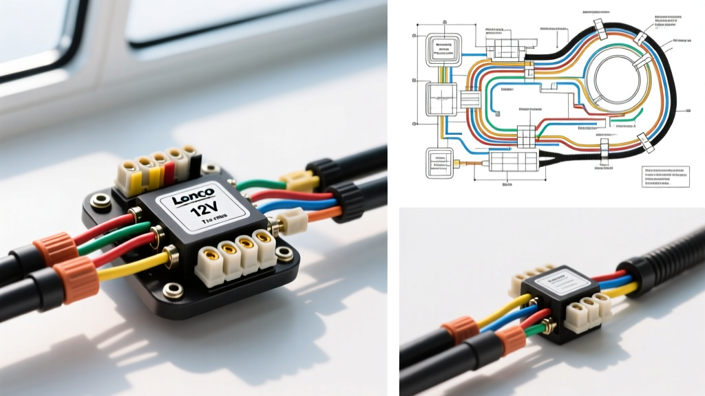
Introduction to 12V DC Actuator Systems in Marine and Amphibious Vehicles
While Lenco trim tabs are predominantly recognized in the marine industry, their 12V DC actuator systems are frequently integrated into custom amphibious truck builds, specialized off-road watercraft, and heavy-duty marine transport vehicles. Understanding the Lenco trim tabs wiring diagram is critical for any automotive or marine electrical technician, as the principles of high-amperage reversible DC motors directly mirror those found in automotive power windows, liftgates, and winch systems. Unlike standard single-direction automotive accessories, trim tab actuators require a polarity-reversing circuit to control extension and retraction. This comprehensive walkthrough details the exact wire color codes, AWG sizing requirements, DPDT switch pinouts, and heavy-duty relay upgrades necessary to build a robust, failure-resistant 12V trim tab system that adheres to both SAE and ABYC electrical standards.
Core Components of the Lenco Wiring Harness
Before tracing the wiring diagram, it is essential to identify the core components of a standard Lenco 12V electric trim tab system. The architecture relies on permanent magnet DC motors that change direction based on the polarity of the voltage applied. The primary components include:
- Lenco 12V DC Actuators: Sealed, reversible permanent magnet motors. Standard models draw between 8A and 12A under normal load, but can spike to 20A–25A under stall conditions (e.g., when the tab hits the water at high speeds or reaches its physical limit).
- DPDT Control Switch: A Double-Pole, Double-Throw (DPDT) momentary ON-OFF-ON switch. This specific switch topology is required to cross the positive and negative feeds, effectively reversing the polarity to the actuator.
- Main Circuit Protection: A 30A manual-reset marine-grade circuit breaker or a high-amp ATC/ATO blade fuse block located within 7 inches of the positive battery terminal.
- Wiring Harness: Typically utilizes 10 AWG for main power runs and 14 AWG for switch control circuits, insulated to SAE J1128 standards for resistance to moisture, oil, and heat.
Actuator Motor Specifications & Polarity Reversal
Each Lenco actuator features two primary leads. Because the motor is reversible, there is no dedicated 'positive' or 'negative' wire on the actuator itself; direction is entirely dictated by the harness. In standard Lenco color-coded harnesses, the wire assignments are as follows:
- Port Actuator: Blue (Retract/Up) and White (Extend/Down)
- Starboard Actuator: Green (Retract/Up) and Yellow (Extend/Down)
Applying 12V+ to the Blue or Green wire will cause the respective actuator to retract the trim tab. Applying 12V+ to the White or Yellow wire will extend the tab. The ground path is completed through the opposing wire back to the DPDT switch, which routes it to the vehicle's main negative bus.
Complete Lenco Trim Tabs Wiring Diagram Walkthrough
The following section breaks down the physical routing and termination of the wiring diagram, moving from the vehicle's battery to the transom-mounted actuators.
Step 1: Power and Ground Distribution (AWG Sizing)
Voltage drop is the leading cause of premature actuator failure in 12V vehicle systems. According to ABYC E-11 Electrical Standards, a 3% voltage drop is the maximum allowable limit for critical navigation and control systems. For a standard 15-foot round-trip wire run from the battery to the transom:
- Main Power Feed: Use 8 AWG SGT/SGX battery cable from the positive battery terminal to a 30A circuit breaker, then transition to 10 AWG GXL wire to the DPDT switch. The larger 8 AWG cable mitigates voltage drop over the initial long run through the engine bay.
- Ground Distribution: Do not rely on local chassis or hull grounds for the actuators. Run a dedicated 10 AWG ground wire from the DPDT switch back to the vehicle's main negative bus bar or the engine block ground stud. Torque the ground stud to the manufacturer's specification (typically 15-20 ft-lbs for 3/8-inch studs) to prevent micro-arcing.
Step 2: DPDT Control Switch Pinouts and Cross-Wiring
The DPDT switch is the heart of the Lenco trim tabs wiring diagram. A standard DPDT switch has six terminals, usually arranged in two rows of three. The center row receives the constant 12V power and ground, while the top and bottom rows route the switched power to the actuators. To achieve polarity reversal, the top and bottom terminals must be cross-wired (an 'X' pattern).
| Terminal | Connection Type | Wire Color / Source | Function |
|---|---|---|---|
| Center Left | 12V+ Input | 10 AWG Red (from Breaker) | Constant Switched Power |
| Center Right | Ground Input | 10 AWG Black (to Bus) | Constant Ground Path |
| Top Left | Output 1 | 14 AWG Blue (Port Retract) | Cross-wired to Bottom Right |
| Top Right | Output 2 | 14 AWG White (Port Extend) | Cross-wired to Bottom Left |
| Bottom Left | Output 3 | 14 AWG Green (Stbd Retract) | Cross-wired to Top Right |
| Bottom Right | Output 4 | 14 AWG Yellow (Stbd Extend) | Cross-wired to Top Left |
Note: The exact terminal numbering may vary by switch manufacturer (e.g., Carling Technologies vs. Cole Hersee). Always verify continuity with a multimeter before applying power. The 'X' cross-wiring ensures that when the switch is toggled UP, the left center terminal connects to the top left, and the right center connects to the top right, while the bottom terminals remain isolated.
Heavy-Duty Relay Upgrade for High-Stall Loads
While the direct DPDT switch wiring diagram works for standard applications, automotive electrical experts highly recommend upgrading to an H-Bridge relay configuration for heavy-duty amphibious vehicles or vessels operating in rough conditions. When a Lenco actuator stalls against heavy hydrodynamic load, the inrush current can exceed 25A. Over time, this arcing will pit and destroy the copper contacts inside a standard DPDT rocker switch.
By utilizing four automotive-grade Bosch-style 5-pin relays (one for each directional function), you move the high-amperage load away from the dashboard switch. The switch only carries the low-amperage coil trigger current (under 1A).
Bosch Relay Pinout Integration
- Pin 30 (Common): 10 AWG from the main 30A breaker (Power) or Main Ground Bus.
- Pin 87 (Normally Open): 10 AWG directly to the Actuator Wire (Blue, White, Green, or Yellow).
- Pin 86 (Coil +): 14 AWG from the DPDT switch output.
- Pin 85 (Coil -): 14 AWG to ground (for power-side relays) or 14 AWG to the opposing switch leg (for ground-side relays).
- Pin 87a (Normally Closed): Unused and insulated in this specific H-Bridge configuration.
This relay setup ensures that the SAE J1128 compliant wiring operates well within its thermal limits, drastically extending the lifespan of both the switch and the actuator motors.
Automotive-Grade Integration & Best Practices
Integrating marine components into automotive or amphibious environments requires strict adherence to environmental sealing protocols. The engine bay and transom areas are subjected to extreme thermal cycling, vibration, and corrosive elements.
Connector Selection and Termination
Avoid standard vinyl-insulated crimp connectors. Instead, utilize Deutsch DT series connectors or marine-grade adhesive-lined heat shrink terminals. When terminating the 10 AWG actuator wires at the transom:
- Strip the wire using a precision wire stripper to avoid nicking the copper strands, which creates a focal point for corrosion and voltage drop.
- Use a closed-barrel, marine-grade heat shrink crimp terminal (e.g., Ancor or Tesa).
- Crimp using a ratcheting crimper calibrated for 10 AWG. The crimp should pass a 15 lb pull-test.
- Apply heat evenly until the adhesive sealant purges from the ends of the heat shrink tubing, ensuring a completely waterproof seal.
- Apply a small amount of dielectric grease to the mating pins before connecting the Deutsch plug to the actuator pigtail.
Troubleshooting Common Actuator Failures
When a trim tab system fails, technicians often mistakenly replace the actuator when the fault lies within the wiring diagram's control circuit. Use the following symptom-cause-fix decision tree to accurately diagnose 12V Lenco system failures.
Symptom-Cause-Fix Decision Tree
- Symptom: Port tab extends but will not retract. Starboard tab operates normally.
- Cause: Loss of continuity on the Blue (Port Retract) wire, or a pitted contact inside the DPDT switch on the top-left terminal.
- Fix: Disconnect the switch harness. Use a multimeter to test for continuity between the Blue wire at the transom and the top-left switch terminal. If continuity is present, replace the DPDT switch. If open, locate the break or corrosion point in the Blue wire harness.
- Symptom: Actuator motor hums loudly but the tab does not move.
- Cause: Severe voltage drop (below 10.5V at the actuator under load) or a mechanical bind in the actuator ram.
- Fix: Pierce the actuator wire with a T-pin and measure DC voltage while the switch is depressed. If voltage drops below 11V, check all ground connections and upgrade the wire gauge. If voltage is a solid 12.5V+, the mechanical upper/lower limit switches or the actuator gears are bound; replace the actuator.
- Symptom: Both tabs operate in reverse of the switch indicators (Up button extends the tabs).
- Cause: The main power and ground inputs on the center terminals of the DPDT switch are reversed.
- Fix: Swap the 12V+ Red wire and the Ground Black wire on the two center terminals of the DPDT switch.
- Symptom: System blows the 30A main fuse immediately upon depressing the switch.
- Cause: A dead short in the wiring harness, typically where the wires pass through the transom or bulkhead without a rubber grommet, causing the insulation to chafe against bare metal.
- Fix: Inspect all bulkhead pass-throughs. Repair the chafed wire, install a proper rubber grommet, and apply split-loom corrugated tubing for abrasion resistance.
Authoritative References
For further technical specifications regarding 12V DC vehicle and marine electrical systems, consult the following authoritative resources:
- ABYC (American Boat and Yacht Council) E-11 Standards - The definitive guide for AC and DC electrical systems on marine vehicles, detailing overcurrent protection and wire ampacity charts.
- SAE J1128 Low Tension Primary Cable - The Society of Automotive Engineers standard for wire insulation types, temperature ratings, and physical dimensions used in automotive and marine crossover applications.
- Lenco Marine Official Installation Manuals - Manufacturer-specific wiring diagrams, actuator torque specifications, and troubleshooting flowcharts for all current-generation 12V electric trim tab systems.