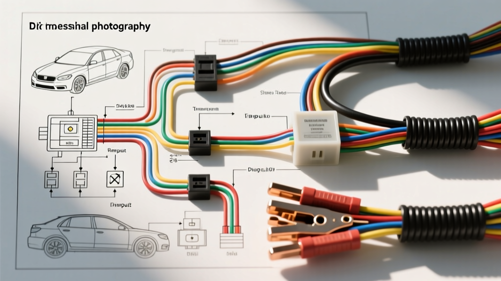
Core Architecture: The Off-Delay Time Delay Relay
When integrating auxiliary lighting, HVAC blower motor delays, or cooling fan post-run systems, a standard ISO mini relay is insufficient. You require a dedicated timing mechanism. Understanding the wiring diagram for time delay relay circuits is critical for diagnosing retained accessory power faults, parasitic battery drains, and premature load shutoffs. Unlike a standard 4-pin relay that reacts instantaneously to a trigger signal, an automotive time delay relay (specifically the 'Off-Delay' or 'Interval' variant) utilizes an internal resistor-capacitor (RC) network or a solid-state microcontroller to maintain the high-current contact closure for a predetermined duration after the trigger signal is removed.
In this guide, we will dissect the 5-pin ISO Off-Delay time delay relay, providing a rigorous, step-by-step troubleshooting flow to isolate control circuit failures, timing capacitor degradation, and high-current load faults.
Standard 5-Pin Time Delay Relay Pinout & Wire Sizing
Before initiating the diagnostic flow, verify that your physical wiring matches the standard 5-pin ISO footprint. According to SAE J553 standards for automotive relays, the pin numbering and terminal assignments must adhere to strict conventions to prevent catastrophic short circuits. Below is the reference specification chart for a standard 30A/40A Off-Delay relay.
| Pin Number | Terminal Function | Typical Wire Color (DIN 72581) | Recommended AWG Size | Max Continuous Current |
|---|---|---|---|---|
| 30 | Common Input (12V+ Battery) | Red (RD) | 10 AWG (up to 30A) | 30A - 40A |
| 87 | Normally Open (Output to Load) | Yellow (YE) | 10 AWG or 12 AWG | 30A - 40A |
| 87a | Normally Closed (Rarely used in timers) | White (WH) | 12 AWG or 14 AWG | 20A |
| 85 | Coil Ground / Trigger Ground | Black (BK) | 16 AWG or 18 AWG | < 1A (Coil Draw) |
| 86 | Trigger Input (Ignition/Switch 12V+) | Blue/White (BU/WH) | 16 AWG or 18 AWG | < 1A (Coil Draw) |
Expert Note: Always use stranded copper wire (SAE J1128 Type GXL or TXL) for automotive applications. Solid core wire will fracture under chassis vibration, leading to intermittent timing failures.
Step-by-Step Troubleshooting Decision Tree
Follow this sequential diagnostic flow to isolate the root cause of your time delay relay malfunction. You will need a digital multimeter (DMM), a stopwatch, and a set of back-probe pins.
Phase 1: Control Circuit & Power Verification (Pins 30, 85, 86)
The most common cause of a 'no-delay' or 'no-power' complaint is a failure in the low-current control circuit or the main battery feed.
- Test Main Battery Feed (Pin 30): Set your DMM to DC Volts. Probe Pin 30 and a known good chassis ground. You must read battery voltage (12.2V - 12.6V engine off; 13.8V - 14.4V engine running). If voltage is low, perform a voltage drop test on the supply wire. A drop greater than 0.2V indicates high resistance or corrosion at the main fuse block.
- Test Trigger Signal (Pin 86): With the ignition ON (or the auxiliary switch engaged), probe Pin 86. You should read full system voltage. If voltage is absent, trace the trigger wire back to the ignition switch or CAN-Bus interface module.
- Test Coil Ground (Pin 85): Switch your DMM to Continuity/Ohms. With the circuit de-energized, probe Pin 85 to the chassis. Resistance should be less than 0.5 ohms. If the relay is triggered by a switched ground (common in ECU-controlled cooling fans), verify that the ECU provides a clean path to ground when active.
Phase 2: Timer Circuit & Logic Validation (The 'Delay' Test)
If the relay clicks ON immediately but fails to stay ON after the trigger is removed, the internal timing circuit has failed. As detailed in the Littelfuse Automotive Relay Application Guide, the internal electrolytic capacitor responsible for holding the coil charge can dry out over years of under-hood heat cycling, drastically reducing the delay time.
- Establish Baseline Timing: Connect a test light or DMM to Pin 87 (Output).
- Energize and Kill: Apply 12V+ to Pin 86. The test light on Pin 87 should illuminate instantly. Now, remove the 12V+ trigger from Pin 86 and start your stopwatch.
- Measure the Decay: The test light should remain illuminated for the relay's specified duration (e.g., 30 seconds, 60 seconds). Once the light extinguishes, stop the timer.
- Diagnosis: If the delay is significantly shorter than specified (e.g., drops from 60s to 4s), the internal RC capacitor has degraded. The relay must be replaced. If the relay stays on indefinitely, the internal solid-state switching transistor has shorted, which will lead to a massive parasitic battery draw.
Phase 3: High-Current Load Circuit & Contact Inspection (Pins 30 & 87)
If the timer counts down correctly, but the load (e.g., HVAC blower motor, off-road light bar) is underperforming or flickering, the high-current contacts are suspect.
- Perform a Loaded Voltage Drop Test: Connect the actual load to Pin 87. Turn the system ON. Place your DMM leads directly on the metal terminals of Pin 30 (source) and Pin 87 (output) while the circuit is under load.
- Evaluate the Drop: According to Aptiv Automotive Electrical Fundamentals, a healthy relay contact should exhibit a voltage drop of no more than 0.1V to 0.2V. If you read 0.5V or higher across the relay, the internal copper contacts are pitted, carbon-fouled, or welded. Replace the relay immediately to prevent a thermal event or melted harness.
Advanced Diagnostics: CAN-Bus Integration & Parasitic Draw
Modern vehicles (2015+) utilize multiplexed CAN-Bus networks and low-current PWM (Pulse Width Modulation) signals to trigger accessories. Connecting a standard time delay relay coil directly to a CAN-Bus taillight circuit or a BCM (Body Control Module) output can trigger 'Bulb Out' errors or hyper-flashing due to the relay coil's initial inrush current and flyback voltage.
The Opto-Isolator Solution
When drafting a wiring diagram for time delay relay integration on modern chassis, you must isolate the timer coil from the OEM data bus. Use an automotive-grade opto-isolator or a solid-state logic relay to read the BCM signal, and use that isolated output to trigger Pin 86 on your heavy-duty time delay relay. Furthermore, ensure a flyback suppression diode (e.g., 1N4007) is installed in reverse bias across Pins 85 and 86 if the time delay relay does not feature internal suppression. This prevents inductive voltage spikes from back-feeding and frying sensitive OEM control modules when the internal timer finally drops the coil ground.
Testing for Parasitic Draw
A failing time delay relay is a notorious culprit for dead batteries. If the internal timer logic board fails in the 'closed' state, Pin 30 remains connected to Pin 87 even when the vehicle is asleep.
- Test Procedure: Set your DMM to the 10A Amperage setting. Disconnect the negative battery terminal and place the DMM in series between the negative post and the cable.
- Wait for Sleep Mode: Allow the vehicle's CAN-Bus to go to sleep (typically 20-45 minutes). Do not open doors or use a key fob during this time.
- Read the Draw: Acceptable parasitic draw is typically under 50mA (0.05A). If you see a draw matching the relay's load (e.g., 5A for a cooling fan), pull the time delay relay from its socket. If the draw instantly drops to normal, the relay's internal timing circuit has suffered a catastrophic short and must be replaced.
Summary of Real-World Failure Modes
Troubleshooting a time delay relay requires looking beyond simple continuity. Heat soak from exhaust manifolds can melt the relay's epoxy casing, causing internal pin misalignment. Vibration can fracture the solder joints connecting the internal timing PCB to the heavy ISO pins. Always mount time delay relays in vertical orientations with the pins pointing downward to prevent water ingress from compromised harness seals, and utilize dielectric grease (such as Nyogel 760G) on the connector terminals to prevent galvanic corrosion that mimics internal timer failure.