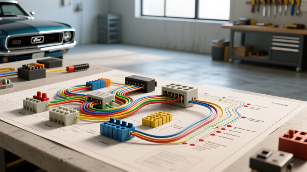
The Hidden Dangers in the 1969 Mustang Wiring Diagram
When working on classic muscle cars, misinterpreting the factory schematic is the leading cause of melted bulkhead connectors, parasitic draws, and catastrophic electrical fires. The 1969 Mustang wiring diagram is a masterpiece of late-1960s Ford engineering, but over 50 years of heat, vibration, and amateur modifications have turned many engine bays into serious safety hazards. Whether you are performing a frame-off restoration or chasing a parasitic battery drain, you must understand the critical failure points of the original Ford unibody electrical architecture. Below, we break down the most dangerous mistakes mechanics make when reading and modifying the 1969 Mustang schematics, complete with OEM wire colors, AWG specifications, and actionable safety fixes.
Mistake 1: The Starter Solenoid 'I' Terminal Trap
One of the most catastrophic misinterpretations of the 1969 Mustang wiring diagram involves the starter solenoid. The factory solenoid features a large 'BATT' post (fed by a heavy 4 AWG Red wire directly from the battery) and a small 'I' (Ignition) terminal. In the OEM schematic, a Brown wire connects to this 'I' terminal. Its sole purpose is to send full 12V to the ignition coil only while the engine is cranking, bypassing the factory Pink resistance wire that normally steps down voltage to 9V for the points-style distributor.
The Dangerous Mistake: Amateur mechanics frequently use this 'I' terminal as a convenient switched 12V source for aftermarket accessories like electric fuel pumps, MSD ignition boxes, or aftermarket gauges.
The Safety Hazard: Because the 'I' terminal is only energized when the key is in the 'Start' position, any accessory wired to it will instantly die the moment you release the key to the 'Run' position. If an electric fuel pump is wired here, the engine will start, but stall seconds later, leaving you stranded or causing unburned fuel to wash the cylinder walls. Furthermore, drawing high amperage through the small 'I' terminal can melt the solenoid's internal contacts.
The Fix: Never use the 'I' terminal for accessories. Instead, use a proper IGN-switched 12V source from the ignition switch harness (Red/Green, 14 AWG) to trigger a 30A Bosch-style relay, which then powers your high-draw accessories directly from the battery.
Mistake 2: Overloading the Headlight Switch Thermal Breaker
The 1969 Mustang utilizes a specific switched-ground headlight system controlled by the floor dimmer switch. The main headlight feed from the dash-mounted headlight switch is a Black/Yellow wire (14 AWG). A critical, often overlooked safety feature in the 1969 diagram is the internal 15-amp thermal circuit breaker housed directly inside the headlight switch assembly.
The Dangerous Mistake: Restorers frequently upgrade to high-draw 100W or 130W Halogen/H4 bulbs without upgrading the wiring or adding relays. They assume the factory 14 AWG wire and Packard 56 series connectors can handle the increased load.
The Safety Hazard: Exceeding the 15A threshold causes the internal thermal breaker to overheat and trip. The headlights will suddenly shut off while driving at night. As the breaker cools, it resets, turning the lights back on, creating a dangerous flickering effect and leaving the driver blind on the highway. Additionally, the excess heat travels back through the bulkhead connector, melting the plastic cowl housing.
The Fix: If upgrading bulbs beyond 65W, you must install a headlight relay harness. Use the factory Black/Yellow wire merely as a low-amp trigger signal for the relays, and run new 10 AWG fused feeds directly from the starter solenoid BATT post to the headlight sockets.
Mistake 3: The Unibody Grounding Fallacy
Ford's unibody construction relies heavily on the sheet metal chassis for ground returns. The 1969 schematic shows various ground straps attaching to the inner fender aprons, engine block, and firewall.
The Dangerous Mistake: Assuming bare metal is a good ground after a fresh paint job, or ignoring surface rust when reattaching ground straps. Many restorers attach the main engine ground strap to a freshly painted inner fender and wonder why their starter draws excessive amperage and their alternator fails to charge.
The Safety Hazard: Paint, powder coat, and rust act as electrical insulators. A poor ground forces the starter motor to pull amperage through alternative paths, such as the throttle cable or heater core hoses, leading to melted cables, arcing, and severe voltage drops that can fry sensitive aftermarket electronics.
The Fix: Always use a wire brush or sanding disc to expose bare, shiny steel at all ground points. Use star washers to bite through any surface oxidation. For high-amperage circuits, run a dedicated 8 AWG or 4 AWG copper ground strap directly from the engine block to the chassis, bypassing the unibody sheet metal entirely.
Mistake 4: Alternator Upgrades and the Missing Sense Wire
Upgrading from the factory 1G alternator (38A or 55A with an external voltage regulator) to a modern 100A+ 3G alternator is a common and necessary modification. However, miswiring the 3G harness is a frequent cause of battery boil-overs.
The Dangerous Mistake: Wiring the Yellow/White stripe 'Sense' wire directly to the alternator's output post (BATT terminal) instead of the battery positive terminal or starter solenoid.
The Safety Hazard: The sense wire tells the internal voltage regulator what the battery is actually receiving. If connected at the alternator, the regulator reads 14.2V at the alternator post. However, due to voltage drop across the 10 AWG charge wire and the bulkhead connector, the battery might only be receiving 13.1V. The alternator will continuously overcompensate, pushing excessive voltage and heat into the system, eventually boiling the battery acid and melting the factory ammeter wiring.
The Fix: Route the Yellow/White sense wire alongside the main 10 AWG charge wire and connect it directly to the battery positive terminal or the starter solenoid BATT post. This ensures the regulator compensates for voltage drop across the wiring harness.
1969 Mustang Critical Circuit Wire Gauges & Fusing Specs
| Circuit | Factory OEM Color | OEM AWG | Max Safe Amp | Upgrade AWG | Relay Required? |
|---|---|---|---|---|---|
| Main Battery Feed | Yellow | 12 AWG | 20A | 10 AWG | No (Fused) |
| Headlight Feed | Black/Yellow | 14 AWG | 15A | 10 AWG | Yes (Mandatory for >65W) |
| Ignition Switch Run | Red/Green | 14 AWG | 15A | 12 AWG | Yes (For MSD/Fans) |
| Alternator Charge | Black/Orange | 10 AWG | 55A | 8 AWG | No (Fusible Link) |
| Starter Solenoid BATT | Red | 4 AWG | 150A+ | 2/0 AWG | No |
Symptom-Cause-Fix Decision Tree for Classic Ford Electrical Faults
- Symptom: Headlights flicker off and on while driving at night.
Mistake: Upgraded to 100W Halogen bulbs on the factory 14 AWG Black/Yellow harness.
Fix: The internal 15A thermal breaker in the headlight switch is tripping. Install a 30A Bosch-style relay kit triggered by the factory dimmer switch, and run new 10 AWG direct battery feeds to the sockets. - Symptom: Engine stalls immediately after releasing the key from 'Start' to 'Run'.
Mistake: Electric fuel pump wired to the starter solenoid 'I' (Brown wire) terminal.
Fix: Relocate the fuel pump trigger to an IGN-switched 12V source (Red/Green wire) utilizing a 30A relay to handle the pump's startup amperage surge. - Symptom: Slow cranking and dim dash lights, but battery tests at 12.6V.
Mistake: Poor unibody ground connection due to paint or rust on the engine block ground strap.
Fix: Remove the ground strap, sand the mating surface to bare metal, apply a dielectric grease perimeter to prevent corrosion, and reinstall using a star washer.
Authoritative References & Standards
When restoring or modifying classic automotive electrical systems, always adhere to modern safety standards. For wire insulation and temperature ratings, consult the SAE J1128 Standard for Low Tension Primary Cable. For factory-specific wiring schematics, bulkhead connector pinouts, and original equipment part numbers, the definitive resource is the Marti Auto Works Ford Master Parts Catalog. For step-by-step physical routing and connector crimping procedures, refer to the Haynes Ford Mustang Repair Manual.