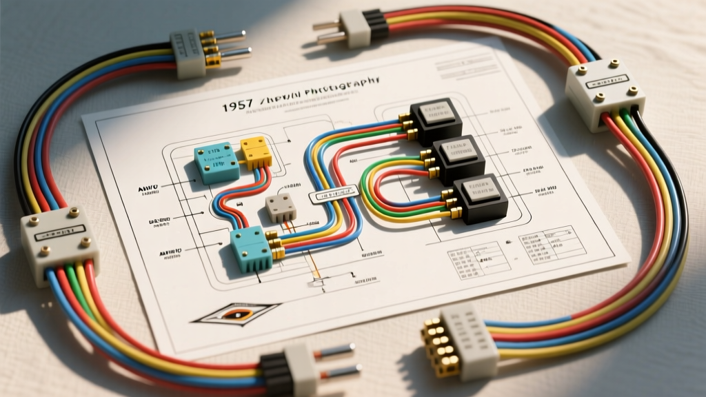
The Shift to 12 Volts: Understanding the 1957 Chevy Architecture
The 1957 Chevrolet passenger car lineup—including the iconic Bel Air, 210, and 150 models—marked a pivotal engineering shift for General Motors. While the 1955 and 1956 'Tri-Five' models relied on 6-volt electrical systems, the 1957 Chevy wiring diagram reflects GM's first widespread implementation of a 12-volt architecture in passenger vehicles. This transition allowed for smaller, higher-cranking-amperage batteries, more reliable starting systems, and brighter incandescent lighting. However, interpreting the factory schematic requires a deep understanding of early 12V Delco-Remy components, cloth-braided wire insulation, and the infamous single-point firewall bulkhead connector.
For restomod builders and concours restorers alike, navigating the original harness requires distinguishing between stock generator regulation and modern alternator retrofits. Below, we break down the core circuits, wire color codes, and critical failure points inherent to the 1957 Chevrolet electrical system.
Bulkhead Connector and Firewall Pass-Through
The most critical chokepoint in the 1957 Chevy wiring harness is the firewall bulkhead connector. Unlike modern vehicles that utilize multiple sealed multi-pin connectors, the '57 Chevy routes nearly the entire cabin-to-engine-bay harness through a single, rectangular mass connector. Over decades of heat cycling and moisture exposure, the brass male and female terminals oxidize, leading to severe voltage drops, particularly on the headlight and ignition circuits.
When restoring or repinning this connector, it is imperative to use modern GXL (Cross-Linked Polyethylene) or TXL wire, which offers superior heat resistance and a thinner outer diameter compared to the original cloth-braided or early PVC wiring, while maintaining the correct AWG ratings for 12V current loads.
Firewall Pinout and AWG Specifications
The following table outlines the primary circuits passing through the engine-side to cabin-side bulkhead, based on factory GM assembly manuals and 1957 Chevrolet Passenger Car Service Manual schematics.
| Circuit Function | Factory Wire Color | AWG Size | Connector Pin / Notes |
|---|---|---|---|
| Main Battery Feed (Ammeter) | Red | 10 AWG | Heavy spade; carries full alternator/generator output |
| Ignition Switch Feed | Pink | 12 AWG | Routes to coil (+) and fuse block accessory feeds |
| High Beam Headlights | Dark Blue | 10 AWG | From floor dimmer switch to front lamp junction |
| Low Beam Headlights | Light Green | 10 AWG | From floor dimmer switch to front lamp junction |
| Tail & Parking Lights | Brown | 14 AWG | Splits at rear body harness junction block |
| Horn Relay Trigger | Dark Green | 16 AWG | From steering column horn ring to relay coil |
| Instrument Cluster Feed | White | 16 AWG | Switched 12V for gauges and radio illumination |
Generator vs. Alternator: Regulator Pinouts and Charge Circuits
A stock 1957 Chevy utilizes a Delco-Remy external voltage regulator paired with a DC generator. While adequate for 1950s electrical loads (minimal accessories, no high-draw audio), it fails to support modern EFI systems, electric cooling fans, or high-output A/C compressors.
The Factory External Voltage Regulator
The stock generator relies on a 4-terminal mechanical regulator mounted on the inner fender. The terminals are designated as follows:
- BAT (Battery): Receives 12V+ from the starter solenoid/battery junction. Used for the internal voltage sensing coil.
- ARM (Armature): Connects to the generator's armature terminal. Monitors generator output to prevent overcharging.
- FLD (Field): Supplies pulsed 12V+ to the generator's field windings to excite the stator and initiate charging.
- GND (Ground): Must be grounded directly to the inner fender using a star washer to ensure bare metal contact.
Upgrading to a 12SI Internally Regulated Alternator
The most common and reliable upgrade for the '57 Chevy is swapping the generator for a GM 12SI internally regulated alternator (typically rated at 63 to 94 amps). As detailed by the experts at MAD Electrical, the 12SI requires a specific 2-pin plug (Terminals 1 and 2) to function correctly without triggering the dash 'GEN' warning light prematurely.
- Terminal 1 (Sense/Excite): Must be wired to a switched 12V+ source (like the pink ignition wire or the instrument cluster warning lamp). This provides the initial 'excitation' current to the rotor.
- Terminal 2 (Voltage Sense): Should be jumpered directly to the alternator's main BAT output post, or run to the positive battery terminal for precise voltage sensing at the battery.
Critical Safety Note: When performing this swap, the original 10 AWG generator charge wire is insufficient for a 94-amp alternator. You must upgrade the main charge wire to a minimum of 4 AWG or 6 AWG stranded copper, fused at 100A within 8 inches of the starter solenoid connection, in accordance with SAE J1128 Low Tension Primary Cable standards.
Addressing Voltage Drop: Headlight Relay Integration
In the factory 1957 Chevy wiring diagram, the full current load for the headlights (approximately 10 to 12 amps per pair) passes directly through the headlight switch on the dash, down to the floor-mounted dimmer switch, and back out to the front of the vehicle. This long circuit run using 60-year-old copper and aging bulkhead pins inevitably results in a severe voltage drop, yielding dim, yellowish headlights.
To resolve this while maintaining factory switch functionality, integrate a dual-relay harness using standard Bosch-style 12V 30/40A SPDT relays:
- Trigger Circuit (Pins 85 & 86): Tap the original Dark Blue (High) and Light Green (Low) wires at the dimmer switch to act as the low-amp trigger signals for the relay coils. Ground Pin 85 of both relays to the chassis.
- Load Circuit (Pins 30 & 87): Run a new, fused 10 AWG feed directly from the battery positive (or starter solenoid) to Pin 30 on both relays. Run new 10 AWG wires from Pin 87 on each relay directly to the respective headlight bulb terminals.
This modification ensures the headlights receive a full 14.2V (engine running), vastly improving lumen output and reducing thermal stress on the vintage dashboard headlight switch.
Grounding Protocols and Ammeter Safety
The 1957 Chevy dashboard houses an ammeter wired in series with the entire charging system. All current generated by the alternator flows through the back of the dash gauge before reaching the battery. If the spade connections on the back of the ammeter loosen or corrode, the high amperage will arc, melt the plastic gauge housing, and frequently ignite the under-dash insulation.
The Modern Restomod Fix: Bypass the ammeter for main charging duties. Run your heavy 4 AWG alternator charge wire directly to the starter solenoid (battery side). Convert the dash ammeter to a voltmeter, or wire the ammeter in parallel with a heavy-duty shunt so it only reads accessory draw, completely eliminating the fire hazard of routing 100+ amps through the dashboard.
Furthermore, ensure the engine block is grounded to the firewall using a minimum 2/0 AWG braided copper ground strap, and the firewall is grounded to the chassis frame. Star washers must be used on all ground termination points to bite through paint and powder coating, ensuring a zero-ohm return path to the battery negative.