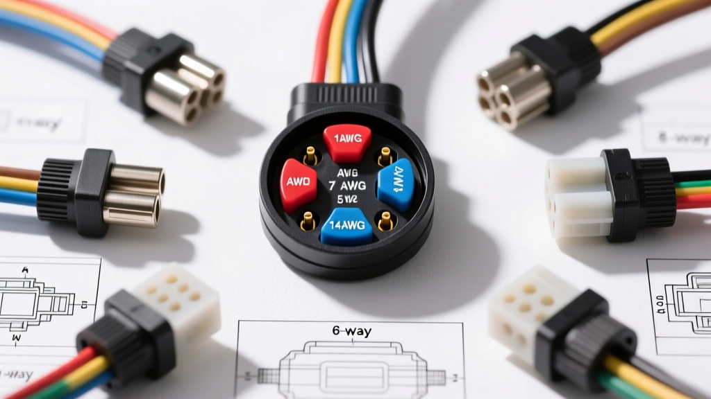
Selecting the Correct Wiring Diagram for Trailers: A Comprehensive Comparison
When towing anything from a light-duty utility trailer to a 10,000-lb GVWR travel trailer, selecting the correct wiring diagram for trailers is not just a matter of convenience—it is a critical safety requirement. The connector you choose dictates your ability to activate electric brakes, illuminate running lights, and supply auxiliary 12V power to onboard batteries. According to the Recreational Vehicle Industry Association (RVIA) and SAE International standards, mismatched pinouts or undersized wire gauges are the leading causes of trailer electrical fires and brake failures.
This product comparison and selection guide breaks down the four primary trailer connector types, detailing their specific applications, SAE-compliant wire color codes, and exact pin configurations. Whether you are wiring a new flatbed or troubleshooting an existing RV harness, understanding these schematics ensures your tow vehicle and trailer communicate flawlessly.
The 4-Way Flat Connector: Light-Duty & Utility Applications
The 4-way flat connector is the most ubiquitous wiring diagram for trailers under 3,000 lbs GVWR. It is designed strictly for basic lighting functions and does not support electric brakes or auxiliary 12V charging. Because it lacks a dedicated ground pin on the connector itself (relying instead on the white wire routed to the trailer frame), it is highly susceptible to ground-loop issues if the trailer frame is painted or rusted.
4-Way Flat Pinout & Color Code
| Pin Position | Function | SAE Standard Wire Color | Recommended AWG |
|---|---|---|---|
| Ground (Shield) | Chassis Ground | White | 14 AWG |
| Left (Driver) | Tail / Running Lights | Brown | 16 AWG |
| Center 1 | Left Turn / Stop | Yellow | 16 AWG |
| Center 2 | Right Turn / Stop | Green | 16 AWG |
Expert Insight: Never rely on the hitch ball for your ground return path. Always run a dedicated 14 AWG white ground wire from the 4-way connector directly to a clean, bare-metal surface on the trailer tongue, secured with a star washer and treated with dielectric grease.
The 5-Way Flat Connector: Adding Reverse Lockout
The 5-way flat connector builds upon the 4-way design by adding a fifth pin, typically colored blue. This pin is specifically designated for the reverse lockout solenoid on surge brake systems. When the tow vehicle is shifted into reverse, the 5-way sends 12V to the trailer's surge brake coupler, disengaging the brakes so the trailer can be backed up without locking the wheels.
While the wiring diagram for trailers with 5-way connectors is straightforward, installation requires tapping into the tow vehicle's reverse light circuit. This is usually done using a PWM-compatible relay or a dedicated reverse lockout module to prevent backfeeding voltage into the vehicle's CAN-bus system, which can trigger dashboard warning lights on modern trucks.
The 6-Way Round Connector: Equestrian and Heavy Utility
The 6-way round connector is frequently found on horse trailers and older heavy-duty utility trailers. It adds electric brake control and a 12V auxiliary circuit to the standard lighting functions. However, the 6-way round suffers from a lack of universal standardization regarding the center pin. In some wiring diagrams, the center pin is designated as the 12V auxiliary power, while in others, it is the electric brake output. Always verify the tow vehicle's 6-way pinout with a multimeter before plugging in a 6-way trailer to prevent sending 12V continuous power directly into the trailer's brake magnets, which will instantly overheat and destroy them.
The 7-Way RV Blade: Heavy-Duty and Brake Controller Standard
For any trailer equipped with electric brakes or requiring a 12V charge line for breakaway batteries and interior accessories, the 7-way RV blade is the undisputed industry standard. Governed by SAE J286 and RVIA guidelines, the 7-way blade offers a standardized, weather-resistant layout that separates high-current brake circuits from low-current lighting circuits.
7-Way RV Blade Pinout & Specification Chart
| Pin / Clock Position | Function | Wire Color | Max Load / AWG Spec |
|---|---|---|---|
| Center | Chassis Ground | White | 10 AWG (Up to 30A) |
| 12 o'clock | Tail / Marker Lights | Brown | 14 AWG (15A Max) |
| 2 o'clock | Right Turn / Stop | Green | 14 AWG (15A Max) |
| 4 o'clock | Electric Brakes | Blue | 10 AWG (Up to 30A) |
| 6 o'clock | 12V Auxiliary Power | Black | 10 AWG (Up to 30A) |
| 8 o'clock | Left Turn / Stop | Yellow | 14 AWG (15A Max) |
| 10 o'clock | Auxiliary / Reverse | Purple | 14 AWG (15A Max) |
Wire Gauge (AWG) Selection & Voltage Drop Mitigation
A common failure point when executing a wiring diagram for trailers is ignoring voltage drop over the length of the trailer harness. A 25-foot trailer effectively doubles the wire length to 50 feet when accounting for the ground return path. According to standard electrical engineering principles, pushing 15 amps through 50 feet of 16 AWG copper wire results in a voltage drop of nearly 3 volts. This leaves only 9 volts at the trailer's LED or incandescent lights, causing dimming and triggering hyper-flashing on the tow vehicle.
Trailer Wiring AWG Selection Guide
- 10 AWG (Primary High-Current): Mandatory for the White (Ground), Blue (Electric Brakes), and Black (12V Aux) circuits. Use SAE J1128 compliant stranded copper.
- 12 AWG (Medium-Current): Recommended for long trailers (over 30 feet) for the Brown (Tail) circuit to prevent voltage drop across multiple marker lights.
- 14 AWG (Standard Lighting): Acceptable for Yellow (Left Turn) and Green (Right Turn) circuits on trailers under 25 feet in length.
- 16 AWG (Light-Duty): Only use for short jumper wires between individual LED marker lights. Never use 16 AWG for the main harness run.
Wire Jacket Materials: PVC vs. XLPE
When sourcing wire for your trailer harness, the jacket material is just as critical as the copper gauge. Standard PVC (Polyvinyl Chloride) jacketed wire is inexpensive but highly susceptible to UV degradation, cracking, and brittleness when exposed to extreme cold and road salt. For professional and heavy-duty applications, specify XLPE (Cross-Linked Polyethylene) or TXL/STX wire types. XLPE offers superior abrasion resistance, withstands higher engine-bay temperatures, and resists the micro-fractures that lead to copper oxidation and intermittent short circuits.
Real-World Troubleshooting: Grounding and Pin Corrosion
Even with a perfect wiring diagram for trailers, environmental factors will eventually degrade the system. Use this diagnostic decision tree to isolate the most common trailer wiring failures:
Symptom: Trailer Lights Flicker or Dim When Brakes are Applied
- Cause: Voltage drop due to an undersized ground wire or a corroded hitch ball ground.
- Fix: Verify the white ground wire is a minimum of 12 AWG. Sand the trailer frame grounding point down to bare steel, apply a zinc-rich primer, and secure with a stainless steel ring terminal and star washer.
Symptom: Left Turn Signal Activates the Right Tail Light
- Cause: 'Backfeeding' caused by a poor ground at the trailer's rear light assembly. The current seeks an alternative path to ground through the opposing filament.
- Fix: Run a dedicated 14 AWG white ground wire directly to each individual tail light housing. Do not rely on the trailer's rear steel crossmember for lighting grounds, as pivot points and rust interrupt continuity.
Symptom: Electric Brakes Feel Weak or Pulsing
- Cause: High resistance in the blue brake circuit or corroded 7-way blade pins.
- Fix: Clean the 7-way blade with electrical contact cleaner and a brass wire brush. Apply a thin layer of silicone dielectric grease to the pins to prevent moisture ingress. Check all inline butt connectors; replace standard vinyl crimps with adhesive-lined, dual-wall heat shrink crimps to prevent capillary water wicking.
Conclusion
Selecting the right wiring diagram for trailers requires matching the connector type to your specific towing needs while strictly adhering to SAE wire color codes and AWG specifications. Whether you are utilizing a simple 4-way flat for a landscaping trailer or a full 7-way RV blade for a heavy-duty travel trailer, prioritizing high-quality XLPE wire, dedicated ground circuits, and weather-sealed terminations will ensure a safe, reliable, and legally compliant tow setup for years to come. For further technical standards, always consult the National Highway Traffic Safety Administration (NHTSA) towing guidelines and your specific vehicle manufacturer's trailering supplement.