Why Residential Diagrams Fail in Mobile Environments
When DIY van builders and RV technicians search for a standard residential wiring diagram for bathroom fan and light, they frequently make the critical mistake of applying 120V AC alternating current logic to a 12V DC direct current mobile environment. In a stick-built home, a bathroom exhaust fan and vanity light operate on high-voltage, low-current AC power, allowing the use of thin 14 AWG solid copper wire over long distances with minimal voltage drop. However, in a campervan, travel trailer, or expedition truck, the electrical system relies on a 12V DC battery bank. Because voltage is significantly lower, the current (amperage) required to deliver the same wattage is exponentially higher. This fundamental difference dictates a completely different approach to wire sizing, circuit protection, and switching logic.
Furthermore, vehicles are subjected to constant vibration, extreme temperature fluctuations, and high-humidity environments—especially in a 'wet bath' RV configuration where the shower, toilet, and sink share the same enclosed space. Standard residential wire nuts and untinned copper wire will rapidly succumb to galvanic corrosion and vibration-induced fatigue. This comprehensive guide provides a vehicle-specific, 12V DC wiring diagram and installation protocol designed for marine and RV applications, ensuring your bathroom ventilation and lighting systems operate reliably for years.
System Architecture: The 12V DC Branch Circuit
Before running any wire, you must understand the load profile of your specific devices. A high-performance RV roof vent fan (such as a MaxxAir or Fan-Tastic Vent) typically draws between 2.5A and 4.0A at 12V DC, while a modern LED bathroom vanity mirror or ceiling puck light draws between 0.5A and 1.5A. Assuming a combined maximum continuous load of 6.0A, we must size our components to handle a 25% safety buffer, bringing our design target to 7.5A.
| Component | Specification | Engineering Purpose |
|---|---|---|
| Primary Wire | 14 AWG Stranded Tinned Copper | Handles up to 15A safely; tinning prevents black oxide corrosion in wet baths. |
| Circuit Protection | 10A ATO Blade Fuse | Protects the branch circuit wiring from thermal overload and short circuits. |
| Switching Hardware | 20A DPST Marine Rocker Switch | Handles the inductive voltage spike generated when the fan motor starts. |
| Relay (Optional) | 12V 4-Pin ISO Automotive Relay | Eliminates voltage drop on wire runs exceeding 15 feet from the busbar. |
| Terminations | Adhesive-Lined Heat Shrink | Creates a waterproof, vibration-proof seal over crimped connections. |
Step-by-Step Installation Guide
Phase 1: Power Distribution and Fusing
Never connect a branch circuit directly to the vehicle's battery terminals. All 12V DC loads must originate from a fused distribution busbar. This ensures that the main Class T fuse and battery shunt can accurately monitor your state of charge and protect the entire system. From your positive busbar, run a length of 14 AWG red (or yellow, per marine standards) tinned copper wire. Install a 10A ATO blade fuse holder as close to the busbar as physically possible. This protects the entire length of the wire run leading to the bathroom. According to Blue Sea Systems circuit protection guidelines, the fuse must be rated to protect the wire, not just the load. Since 14 AWG wire is rated for roughly 15A in an engine space and up to 25A in open air, a 10A fuse provides a massive safety margin against chafing-induced short circuits.
Phase 2: Switching Logic and Relay Integration
If your RV's electrical panel is located more than 15 feet away from the bathroom, pushing the full 6A load through a standard wall switch will result in noticeable voltage drop and potential switch overheating due to resistance. In this scenario, the wiring diagram for the bathroom fan and light must incorporate a standard 4-pin automotive ISO relay. The relay allows you to run a low-current 'trigger' wire to the wall switch, while the heavy 12V+ current flows directly from the busbar to the fan and light. Mount the relay in a dry, ventilated area—preferably under a bed or inside a cabinetry void, well away from the shower's moisture envelope. Use a DPST (Double Pole Single Throw) switch if you wish to control the fan and light independently from a single wall plate, or use two separate SPST rocker switches.
Phase 3: Grounding in Non-Metallic Chassis
Unlike standard automotive applications where the steel chassis serves as a reliable ground return path, modern RVs, campervans, and travel trailers are constructed with fiberglass, aluminum composite, and wood. You cannot ground the bathroom fan or light to the wall studs. You must run a dedicated 14 AWG black (or white, per RVIA standards) ground wire all the way back to the negative distribution busbar. Ensure all ground connections on the busbar are torqued to the manufacturer's specification (typically 35-50 in-lbs for 1/4-inch hardware) to prevent high-resistance connections that will cause your LED lights to flicker when the fan motor kicks on.
Standard 4-Pin ISO Relay Pinout Reference
When utilizing a Bosch-style 12V automotive relay to manage long wire runs, strict adherence to the pinout is required to prevent shorting the control circuit.
| Pin Number | Standard Wire Color | Connection Target | Circuit Role |
|---|---|---|---|
| Pin 30 | Red (12 AWG) | Fused Positive Busbar | Main high-current power input |
| Pin 87 | Red (14 AWG) | Fan & Light Positive (+) | High-current output to load |
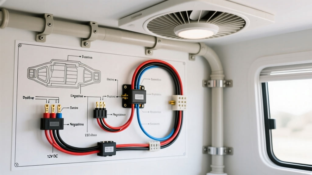
| Pin 86 | Blue (18 AWG) | Wall Switch Output | Low-current trigger signal (12V+) |
| Pin 85 | Black (18 AWG) | Negative Busbar | Relay coil ground return |
Crimping Standards for High-Vibration Environments
In a high-vibration automotive or RV environment, solder-only connections are strictly prohibited by SAE J1128 and ABYC marine standards. Solder creates a rigid point in a stranded wire, leading to work hardening and eventual fatigue failure when the vehicle travels over rough roads. Instead, use a ratcheting crimp tool calibrated for the specific AWG size. For 14 AWG wire, this means using a 16-14 AWG insulated or non-insulated terminal. If using non-insulated terminals, you must cover the connection with adhesive-lined, dual-wall heat shrink tubing. The inner layer of thermoplastic adhesive melts and flows into the wire strands, creating a waterproof seal that prevents galvanic corrosion—a critical factor when wiring a bathroom exhaust fan that will be exposed to high humidity and condensation.
Wire Routing and Moisture Protection in Wet Baths
Routing 12V DC wiring through an RV requires careful planning to avoid chafing against the vehicle's metal ribs or aluminum framing. When passing through bulkheads or metal cross-members, always install rubber grommets or use split-loom corrugated tubing secured with UV-resistant zip ties. Furthermore, the wiring for the bathroom fan and light must be kept at least 2 inches away from any 120V AC inverter cables or shore power lines to prevent electromagnetic interference (EMI), which can cause flickering in low-voltage LED lighting circuits. Inside the bathroom ceiling cavity, secure all wiring with plastic loom clips every 12 inches to prevent the wires from resting against the hot exhaust housing of the roof vent fan.
Troubleshooting: Voltage Drop and Motor Stall
Voltage drop is the number one killer of RV bathroom ventilation systems. A high-performance roof fan drawing 3.5A at 12V requires a minimum of 11.2V to trigger the motor start sequence and overcome initial mechanical resistance. If the wire run from the distribution panel to the bathroom is 25 feet (50 feet round trip), using undersized 16 AWG wire will result in a 1.2V drop, leaving only 10.8V at the fan. The symptoms are distinct: the fan's control board will click, the LED indicator will illuminate, but the motor will stall or hum weakly.
To diagnose this, use a digital multimeter to measure the voltage at the busbar while the fan is attempting to start. Then, measure the voltage directly at the fan's pigtail connector. If the difference exceeds 0.5V, you must upgrade the branch circuit wiring to 12 AWG or relocate the distribution busbar closer to the load. Always verify that your negative busbar ground strap to the battery is free of corrosion, as a poor main ground will mimic a branch circuit voltage drop.