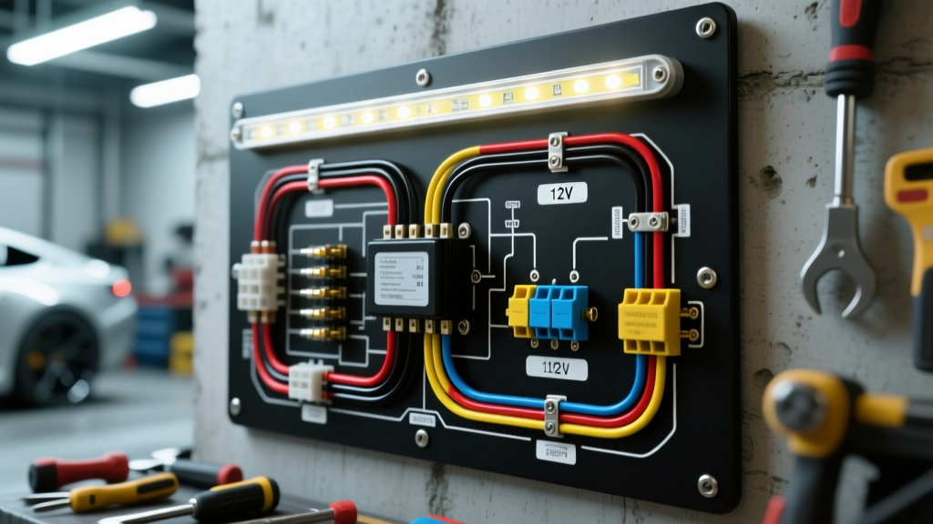
Understanding the Standard LED Light Bar Circuit Architecture
When reviewing a wiring diagram for a LED light bar, the circuit architecture is generally universal across aftermarket 12V DC harnesses. Despite the simplicity of the schematic, environmental factors, vibration, and modern vehicle CAN-bus/PWM systems frequently introduce complex failure modes. A standard harness relies on a Bosch-style ISO mini relay to isolate the high-current load from the low-current cabin switch. This step-by-step troubleshooting flow is designed for automotive technicians and advanced DIYers to systematically isolate faults using a digital multimeter (DMM) and a logical diagnostic sequence.
Required Diagnostic Tools
- Digital Multimeter (DMM): Capable of measuring DC Voltage, Resistance (Ohms), and Continuity.
- Automotive Test Light: For quick 12V+ and ground verification (use a logic probe for CAN-bus circuits).
- Wire Piercing Probes or Back-Pin Probes: To test connector terminals without damaging the wire insulation.
- Deutsch DT Crimping Tool & Heat Gun: For terminal and seal repairs.
System Anatomy & Specification Reference
Before beginning the diagnostic flow, verify that your harness matches the standard specifications outlined below. Undersized wiring is a leading cause of voltage drop, thermal melting, and premature LED driver failure.
| Circuit Segment | Wire Color (Standard) | AWG Size | Max Ampacity (SAE J1128) | Component / Connection |
|---|---|---|---|---|
| Main Battery Feed | Red | 10 AWG | 30A - 40A | Battery (+) to ATC Fuse Holder |
| Fuse to Relay | Red | 10 AWG | 30A - 40A | ATC Fuse to Relay Pin 30 |
| Relay to Load | Black / Red | 10 AWG | 30A - 40A | Relay Pin 87 to DT Connector (+) |
| Load Ground | Black | 10 AWG | 30A - 40A | DT Connector (-) to Chassis Ground |
| Switch Trigger (+) | Yellow / White | 16 AWG | 5A - 10A | Cabin Switch to Relay Pin 86 |
| Switch / Coil Ground | Black | 16 AWG | 5A - 10A | Relay Pin 85 & Switch to Chassis |
Reference: Wire ampacity ratings based on SAE J1128 Low Voltage Primary Cable Standards for single-core, cross-linked polyethylene (XLPE) insulated wire in engine compartment environments.
Phase 1: Power Source & Fuse Verification (The Battery Side)
The most common point of failure in an LED light bar wiring diagram occurs at the primary power distribution point. High-amperage draws combined with under-hood heat can degrade connections.
Step 1.1: Battery and Main Feed Test
- Set your DMM to DC Volts (20V scale).
- Place the black probe on the vehicle battery negative terminal and the red probe on the battery positive terminal. Verify baseline voltage (should be 12.4V - 12.8V engine off, 13.8V - 14.4V engine running).
- Move the red probe to the input side of the inline ATC fuse holder. If voltage reads within 0.1V of the battery baseline, the ring terminal connection at the battery is secure.
Step 1.2: Fuse and Output Verification
- Inspect the ATC/ATO blade fuse visually. According to Littelfuse automotive specifications, a blown fuse will exhibit a severed zinc element.
- With the fuse installed, probe the output side of the fuse holder. You should read identical voltage to the input side.
- Failure Mode: If you have 12V+ at the fuse output, but the light bar does not illuminate, the fault lies downstream at the relay or load. If you have 0V at the fuse output but 12V at the input, the fuse is blown or the female spade connectors inside the fuse holder have lost tension (a common issue with cheap aftermarket harnesses).
Phase 2: The Relay & Switch Circuit (The Control Side)
The Bosch-style ISO 4-pin relay acts as the heavy-duty switch. Pins 30 and 87 handle the high-current load, while Pins 85 and 86 handle the low-current electromagnetic coil.
Step 2.1: Testing the Switch Trigger (Pin 86)
- Locate the relay and identify the trigger wire (usually Yellow or White, 16 AWG) connected to Pin 86.
- Activate the cabin switch. Probe Pin 86 with your DMM red lead (black lead on known good ground).
- You must read full system voltage (12V+). If voltage is absent, the cabin switch is faulty, or the inline switch fuse (usually 3A or 5A) is blown.
Step 2.2: Testing the Coil Ground (Pin 85)
- Set the DMM to Continuity (Ohms).
- Disconnect the relay. Place one probe on the harness connector for Pin 85 and the other on a bare metal chassis point.
- You should read near 0.0 Ohms. High resistance here indicates a corroded ground ring terminal. Clean the chassis contact point with a wire brush and apply dielectric grease.
Step 2.3: Relay Coil Integrity Test
- Remove the relay from the harness.
- Place your DMM probes directly onto the relay's Pin 85 and Pin 86 blades.
- A healthy 12V DC relay coil will typically read between 60 and 90 Ohms. If it reads infinite (OL), the internal coil is open and the relay must be replaced.
Phase 3: Ground Integrity & Load Testing (The Output Side)
If the relay clicks audibly when the switch is engaged, the control circuit is functional. The fault is now isolated to the high-current output circuit (Pin 87) or the light bar itself.
Step 3.1: Voltage Drop Testing the Output Circuit
Voltage drop testing is the most accurate method for diagnosing resistance in the positive feed to the LED bar. According to Painless Performance wiring guidelines, total voltage drop on a 12V lighting circuit should not exceed 0.5V.
- Turn the light bar ON.
- Place the DMM red probe on the output side of the ATC fuse (upstream of the relay).
- Place the DMM black probe on the positive pin of the Deutsch DT connector at the light bar.
- Read the voltage. If the DMM reads more than 0.5V, you have excessive resistance. This is typically caused by undersized wire (e.g., using 14 AWG instead of 10 AWG), a crimped wire suffering from copper oxidation, or loose spade terminals at Relay Pin 30 or 87.
Step 3.2: The Ground Path Verification
- Keep the light bar ON.
- Move the DMM red probe to the negative pin of the Deutsch DT connector.
- Move the black probe to the vehicle battery negative terminal.
- A reading above 0.2V indicates a poor chassis ground. The ground ring terminal must be removed, sanded to bare metal, and re-secured with a star washer to bite through the paint and primer.
Advanced Diagnostics: PWM Interference & Connector Failures
Modern Vehicle PWM Headlight Circuits
Many modern trucks and SUVs (e.g., 2011+ Ford Super Duty, 2015+ Chevy Silverado, and late-model RAM models) utilize Pulse Width Modulation (PWM) to control headlight and high-beam circuits. If your wiring diagram for a LED light bar dictates using the factory high-beam wire as the 12V+ trigger for Pin 86, the rapid on/off pulsing of the PWM signal will cause the relay to chatter violently, or the LED bar to strobe and flicker.
The Fix: You must install a PWM filter module or a 12V DC relay timer delay between the factory headlight wire and the harness switch trigger. Alternatively, run a dedicated 12V+ trigger from an ignition-switched fuse in the cabin fuse box using an Add-A-Circuit fuse tap, bypassing the factory lighting circuit entirely.
Deutsch DT Connector Environmental Failures
The industry standard for LED light bars is the 2-pin or 4-pin Deutsch DT connector. While highly robust, improper assembly leads to moisture ingress and subsequent copper sulfation (green crust on the pins).
- Wedge Lock Verification: Ensure the internal orange or grey plastic wedge lock is fully seated. If the pins back out slightly when mating the connectors, the circuit will arc under high current, melting the housing.
- Silicone Boot Sealing: After crimping the nickel-plated copper contacts, the rear silicone sealing boot must be pushed flush against the connector housing and heat-shrunk. If water breaches this seal, capillary action will draw moisture up the 10 AWG wire strands, corroding the wire from the inside out.
Summary Troubleshooting Decision Tree
- Symptom: Light bar is completely dead. Relay does not click.
Action: Check ATC main fuse -> Check Switch Trigger voltage at Pin 86 -> Check Pin 85 ground continuity. - Symptom: Relay clicks loudly, but light bar remains off.
Action: Check voltage at Relay Pin 87 -> Check voltage at Deutsch DT positive pin -> Inspect light bar internal waterproof driver potting. - Symptom: Light bar is dim or flickers at high RPM.
Action: Perform voltage drop test on 10 AWG positive and negative circuits -> Check for undersized wiring or loose battery ring terminals. - Symptom: Relay chatters rapidly when triggered by factory high-beams.
Action: Install a PWM signal filter or capacitor module on the trigger wire.
By strictly following this diagnostic flow and referencing the OEM wiring diagram for a LED light bar harness, you can systematically eliminate variables, ensuring a reliable, high-output auxiliary lighting system capable of withstanding harsh automotive environments.