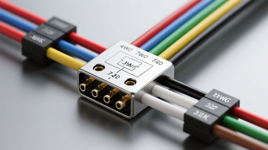
Upgrading from a standard 4-way flat connector to a 7-way RV blade is one of the most common and necessary modifications for truck and SUV owners transitioning from light-duty utility trailers to heavy-duty travel trailers, car haulers, or horse trailers. While a 4-pin setup handles basic lighting, it completely lacks the circuits required for electric trailer brakes, 12-volt auxiliary power for interior trailer accessories, and reverse lockout solenoids for surge brake systems. This comprehensive modification guide provides the exact seven wire trailer plug wiring diagram, American Wire Gauge (AWG) specifications, and step-by-step routing instructions to ensure your tow rig is safely configured for heavy towing.
Why Upgrade to a 7-Way RV Blade Connector?
The primary limitation of the 4-way flat connector is its inability to handle high-amperage auxiliary circuits. When you tow a trailer exceeding 1,500 pounds, most jurisdictions mandate the use of an independent electric or electro-hydraulic trailer brake system. The 4-pin harness simply does not have the physical wire capacity or the dedicated circuit to transmit the pulse-width modulation (PWM) signals from an in-cabin proportional brake controller to the trailer's brake magnets. Furthermore, modern travel trailers require a dedicated 12V power feed to maintain interior lighting, operate water pumps, or keep a breakaway battery charged while in transit. By executing this upgrade project, you align your vehicle's towing package with the SAE J286 standard, ensuring universal compatibility with nearly all North American RVs and heavy equipment trailers.
The Seven Wire Trailer Plug Wiring Diagram and Pinout Chart
When performing this modification, you will be terminating a 7-way RV blade connector (often referred to as a Bargman connector). The physical pin layout is standardized, but mixing up the clock positions during termination is a frequent cause of blown fuses and damaged brake controllers. Below is the definitive pinout reference for the vehicle-side 7-way receptacle.
| Pin Position | Function | Standard Wire Color | Recommended AWG | Circuit Protection |
|---|---|---|---|---|
| 1 (7 o'clock) | Ground Return | White | 8 or 10 AWG | Direct to chassis/frame |
| 2 (5 o'clock) | Electric Brakes | Blue | 10 AWG | 20A or 30A Breaker |
| 3 (1 o'clock) | Tail/Running Lights | Brown | 16 or 14 AWG | 10A Fuse (Vehicle) |
| 4 (9 o'clock) | Left Turn/Stop | Yellow | 16 or 14 AWG | Vehicle BCM/Fuse |
| 5 (11 o'clock) | Right Turn/Stop | Green | 16 or 14 AWG | Vehicle BCM/Fuse |
| 6 (12 o'clock) | 12V Auxiliary Power | Black | 10 AWG | 30A Auto-Reset Breaker |
| 7 (3 o'clock) | Reverse Lights | Red or Purple | 16 or 14 AWG | 10A Fuse (Vehicle) |
Required Materials for the Modification Project
Do not use standard THHN building wire for this project. THHN insulation is not designed for the harsh, wet, and high-vibration environment of a vehicle undercarriage. It will absorb moisture, leading to rapid copper oxidation and severe voltage drop. Instead, source the following automotive-grade materials:
- SXL or GXL Cross-Linked Wire: This insulation type withstands high temperatures, road salt, and abrasion.
- Adhesive-Lined Marine Heat Shrink: Standard heat shrink allows capillary action to draw water into the crimp. Marine-grade shrink contains an inner epoxy that melts and seals the connection completely.
- Ratcheting Crimpers: Never use slip-joint pliers for trailer wiring. A ratcheting crimper ensures a gas-tight mechanical bond that will not vibrate loose.
- 30A and 20A Auto-Reset Circuit Breakers: Essential for the 12V auxiliary (Black) and Electric Brake (Blue) circuits to prevent electrical fires in the event of a short.
- Dielectric Grease: For packing the 7-way receptacle pins to prevent galvanic corrosion.
Step-by-Step 4-Pin to 7-Way Conversion Process
Step 1: Splicing the Base 4-Way Circuit
If your vehicle already has a functioning 4-way flat, you can use a 4-to-7-way adapter harness. However, for a permanent, high-reliability modification, we recommend hardwiring a new 7-way pigtail directly into the existing 4-way circuits using solder-seal heat shrink connectors. Splice the Brown (Running), Yellow (Left), Green (Right), and White (Ground) wires from your new 7-way cable into the corresponding wires of the existing 4-way harness. Ensure the White ground wire is also bonded directly to a clean, bare-metal point on the vehicle's frame using a self-tapping grounding screw and a star washer to bite through the paint and rust.
Step 2: Routing the Heavy-Gauge Brake and Power Circuits
The Blue (Brake) and Black (12V Aux) wires must be routed directly to the vehicle's engine bay; they do not connect to the rear 4-way harness. Run these 10 AWG wires along the vehicle's factory wiring loom, securing them every 12 inches with UV-resistant zip ties. Keep the wiring away from exhaust components, moving suspension linkages, and steering shafts. Once in the engine bay, connect the Black wire to the positive battery terminal via a 30A auto-reset breaker. Connect the Blue wire to the output terminal of your in-cabin electric brake controller, passing through the firewall via a rubber grommet.
Step 3: Terminating the 7-Way Connector
Open the 7-way receptacle housing and strip the wire ends precisely to the terminal depth. Crimp the ring terminals using your ratcheting tool, apply the adhesive-lined heat shrink, and secure them to the corresponding numbered screws inside the plug. Refer back to the seven wire trailer plug wiring diagram chart above to verify clock positions. Once terminated, pack the rear cavity of the plug with dielectric grease before sealing the rubber boot. This prevents moisture ingress, which is the leading cause of internal copper sulfation and pin failure.
Real-World Troubleshooting: Voltage Drop and Ground Failures
The most common failure mode after a DIY 7-way upgrade is erratic trailer lighting or a brake controller displaying a 'C' (Connection) error when no trailer is attached, or failing to output maximum voltage during manual override. According to etrailer's comprehensive wiring diagnostics, over 80% of these issues trace back to an inadequate ground. The White ground wire must be sized appropriately (8 AWG for long trailers) and bonded to bare steel. If the ground relies solely on the trailer hitch ball, the resistance will cause voltage to backfeed through the tail light circuits, resulting in lights that dim when the brakes are applied.
Additionally, voltage drop on the Blue brake wire will result in weak braking performance. If you are towing a triple-axle trailer with six electric brake magnets, the amperage draw can exceed 15 amps. Using 12 AWG wire for this run will cause significant voltage drop by the time the current reaches the trailer's junction box. Always adhere to the 10 AWG minimum for brake circuits. For further technical specifications on brake controller integration and torque specs for terminal screws, consult the Curt Manufacturing towing resources to ensure your modification meets all federal safety guidelines.