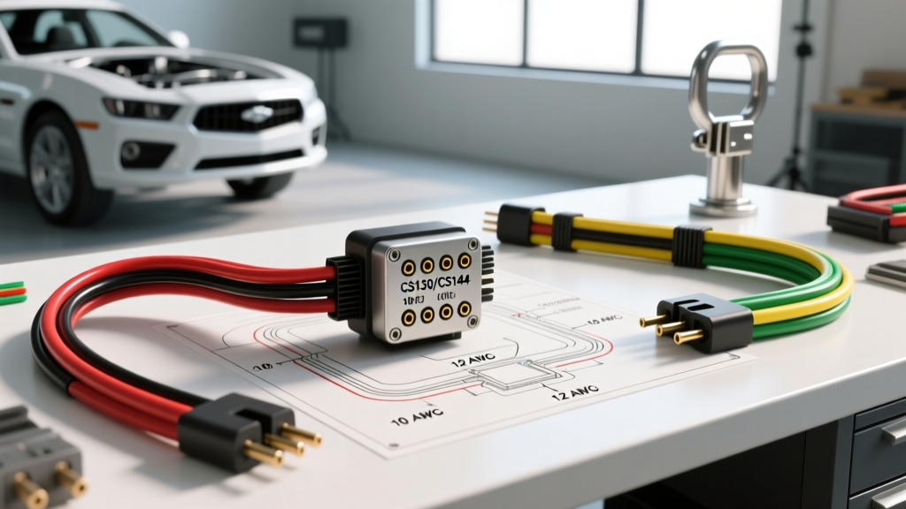
Introduction: Why Your GM Alternator Matters for Towing
When outfitting a GM truck or SUV for heavy towing, understanding your vehicle's charging system is just as critical as understanding your trailer brake controller. Whether you are pulling a dual-axle car hauler or a heavy travel trailer, the electrical demands are immense. Electric trailer brakes can draw up to 15 amps per axle, and the 7-way RV connector requires a dedicated 12V auxiliary feed to keep the trailer's breakaway battery fully charged. At the heart of this system is the GM CS-series alternator, commonly found in vehicles from the late 1980s through the early 2000s.
For beginners and seasoned DIYers alike, mastering the GM 4 pin alternator wiring diagram is the first step toward a reliable towing setup. If your alternator is not properly sensing the voltage drop caused by your trailer's electrical load, your trailer brakes may become sluggish, and your breakaway battery could die on a long descent. This guide breaks down the fundamentals of the GM 4-pin connector, providing actionable wiring advice tailored specifically for heavy-duty trailer applications.
Decoding the GM CS-Series 4-Pin Connector
The GM CS130 and CS144 alternators utilize a specialized 4-pin rectangular connector to communicate with the vehicle's Powertrain Control Module (PCM) and the internal voltage regulator. Unlike older 1-wire or 2-wire setups, this 4-pin system allows for precise voltage regulation based on actual electrical demand—a massive advantage when towing.
The 4-Pin Terminal Reference Chart
| Pin | Terminal Name | Primary Function | Standard Wire Color | Recommended AWG |
|---|---|---|---|---|
| P | Phase | Monitors stator phase voltage; used for tachometer signals or PCM logging. | Yellow / Purple | 16-18 AWG |
| L | Lamp | Provides a ground path through the dash 'ALT' warning lamp to excite the alternator. | Brown / White | 14-16 AWG |
| I | Ignition | Supplies switched 12V power to turn on the internal voltage regulator. | Pink | 12-14 AWG |
| S | Sense | Reads actual battery voltage to adjust alternator output based on real-time load. | Red | 10-12 AWG |
The 'Sense' (S) Pin: The Secret to Trailer Charging
If you are wiring a GM alternator to support a 7-way trailer connector, the S (Sense) pin is the most critical wire in your harness. The internal regulator uses the Sense wire to measure the exact voltage at the vehicle's main battery or primary fuse block.
When you engage your trailer's electric brakes or run heavy auxiliary lights, voltage drops across the vehicle's wiring harness. If the Sense wire is reading the voltage directly at the battery, the alternator will instantly ramp up its amperage output to compensate for the drop, ensuring your trailer's 12V charge line remains at a steady 13.8V to 14.2V. If this wire is damaged, disconnected, or wired incorrectly, the alternator will default to a low-output 'limp mode' (usually around 12.8V), which is insufficient to charge a trailer breakaway battery or run modern proportional brake controllers.
Step-by-Step Towing Setup & Wiring Upgrades
To ensure your GM charging system can handle the parasitic draw of a trailer, follow these beginner-friendly but highly effective wiring upgrades.
1. Upgrade the Main Output (BATT) Terminal
Factory GM wiring often uses 4 AWG or 6 AWG wire from the alternator's rear BATT terminal to the under-hood fuse block. When adding a high-draw 7-way trailer harness, this factory wire can overheat and cause voltage drop.
- Action: Replace the factory output wire with 1/0 AWG pure copper welding cable.
- Routing: Run the 1/0 AWG cable directly from the alternator BATT post to the main battery positive terminal, integrating a 150-amp ANL fuse within 18 inches of the battery.
- Torque Spec: Secure the alternator BATT terminal nut to exactly 85 in-lbs. Overtightening can crack the internal diode bridge casing.
2. Rewiring the Sense (S) Pin for Towing
Do not loop the Sense wire back to the alternator's BATT terminal—a common DIY mistake that defeats the purpose of the 4-pin system.
- Locate the Red Sense wire in the 4-pin pigtail.
- Run a dedicated 10 AWG red wire from the Sense pin directly to the positive side of the vehicle's main fuse block or the battery positive post.
- Install an inline 20-amp maxi-fuse to protect the Sense circuit from shorting to ground.
3. Feeding the 7-Way Trailer Connector
According to etrailer's comprehensive wiring guides, the 12V auxiliary pin (Pin 4 on a standard 7-way) must be fed by a minimum of 10 AWG wire. Run this wire directly from the under-hood fuse block, utilizing a 30-amp circuit breaker. This ensures the alternator's upgraded output reaches the trailer without melting the factory harness.
Common Wiring Mistakes That Fry Trailer Brake Controllers
When working with the GM 4 pin alternator wiring diagram, beginners often make a few specific errors that can lead to catastrophic electrical failures on the road.
- The 'L' Pin Resistor Oversight: If you are swapping a CS130 into an older truck that lacks a dashboard alternator warning light, you must install a 560-ohm, 1/2-watt resistor in parallel with the 'L' wire. Without this resistance, the alternator will not 'excite' and begin charging at idle.
- Using CCA (Copper Clad Aluminum) Wire: Never use CCA wire for the Sense or BATT circuits. CCA has higher resistance than pure copper, which will trick the 'S' pin into reading a lower voltage, causing the alternator to overcharge and boil your battery acid.
- Poor Grounding: The alternator grounds through its mounting bracket to the engine block. If you have painted your engine block or brackets, you must sand the mating surfaces to bare metal. A poor ground will cause alternator 'whine' in your trailer brake controller's PWM (Pulse Width Modulation) signal.
Troubleshooting the GM 4-Pin Circuit
If you have wired the system but are experiencing issues while towing, use this diagnostic tree:
- Symptom: Trailer breakaway battery is dead after a long trip, but vehicle battery is fine.
Fix: Check the 'S' pin wire for corrosion. The alternator is reading high voltage at the block and undercharging the main battery/feed circuit. - Symptom: Alternator whine in the trailer brake controller, or erratic brake application.
Fix: Check the alternator case ground. Add a dedicated 4 AWG ground strap from the alternator casing directly to the negative battery terminal to eliminate AC ripple. - Symptom: The 'ALT' dash light stays on, and the alternator outputs only 12.5V.
Fix: The 'L' circuit is open. Check the dash bulb for a blown filament or test the Brown/White wire for continuity back to the PCM.
Conclusion and Authoritative References
Understanding the GM 4 pin alternator wiring diagram is a foundational skill for any DIY mechanic building a dedicated tow vehicle. By properly configuring the Sense and Ignition circuits, and upgrading the main output wire to handle heavy amperage, you ensure that your trailer's electric brakes and auxiliary systems receive clean, consistent power. Always consult vehicle-specific wiring schematics before cutting into factory harnesses.
For further reading on automotive electrical standards and towing requirements, refer to the following authoritative resources:
- SAE J2807 - Performance Requirements for Determining Tow-Vehicle Gross Combination Weight Ratings (Details electrical and thermal load testing for towing).
- Haynes Repair Manuals - Standard reference for GM CS130/CS144 factory wiring schematics and torque specifications.
- etrailer Wiring FAQ - Industry-standard guidelines for 7-way connector wire gauges and circuit breaker sizing.