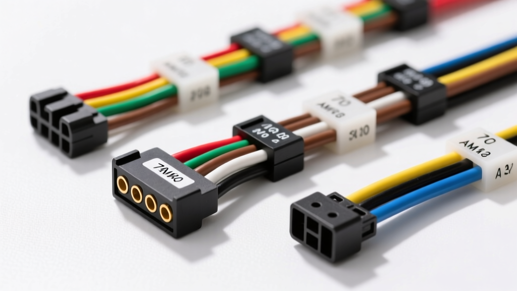
Introduction to Coleman Pop Up Camper Electrical Systems
Owning a Coleman pop-up camper—whether it is a classic Bayside, a rugged Niagara, or a compact Santa Fe—offers an incredible gateway to the outdoors. However, before you hit the highway, understanding your camper's electrical umbilical is critical for safety and legal compliance. The wiring harness connects your tow vehicle's lighting and braking systems to the trailer's running lights, turn signals, and brake lights. For beginners, staring at a tangled mess of copper and corrosion can be intimidating. This comprehensive guide breaks down the standard Coleman pop up trailer wiring diagram into beginner-friendly fundamentals, covering everything from basic 4-pin flat connectors to upgraded 7-pin RV blade configurations, complete with American Wire Gauge (AWG) specifications and real-world troubleshooting matrices.
Decoding the Standard 4-Pin Flat Connector
Most factory-standard Coleman pop-up campers produced from the late 1990s through the 2010s utilize a standard 4-pin flat connector. This configuration is designed exclusively for lighting and does not support electric brakes or auxiliary 12V battery charging. The 4-pin layout follows a strict color code mandated by the Society of Automotive Engineers (SAE) and the National Highway Traffic Safety Administration (NHTSA). Understanding these four wires is the first step in mastering your trailer's electrical system.
4-Pin Wiring Color Code and Function Table
| Pin Position | Wire Color | Function | Recommended AWG |
|---|---|---|---|
| Pin 1 (Ground) | White | Chassis Ground Return | 12 or 10 AWG |
| Pin 2 (Tail/Running) | Brown | Tail Lights, Marker Lights, License Plate | 16 AWG |
| Pin 3 (Left Turn/Stop) | Yellow | Left Turn Signal and Brake Light | 16 AWG |
| Pin 4 (Right Turn/Stop) | Green | Right Turn Signal and Brake Light | 16 AWG |
Expert Insight: The white ground wire is the most common point of failure on Coleman campers. It must be terminated with a ring terminal and bolted directly to a clean, bare-metal section of the trailer's A-frame or main chassis. Never rely on the hitch ball for a ground return, as grease and rust will cause severe voltage drops, resulting in dim or flickering lights.
Upgrading to a 7-Pin RV Blade Connector
While the 4-pin flat is sufficient for basic lighting, many Coleman owners upgrade to a 7-pin RV blade connector (often a Bargman-style plug). This upgrade is highly recommended if your pop-up is equipped with an electric tongue jack, interior 12V appliances, or if you need to charge the onboard Group 24 or 27 marine deep-cycle battery while towing. The 7-pin diagram adds three crucial circuits to the standard lighting setup.
7-Pin Pinout and Wire Gauge Specifications
| Pin Clock Position | Wire Color | Function | Recommended AWG |
|---|---|---|---|
| 1:00 (Ground) | White | Main System Ground | 8 or 10 AWG |
| 3:00 (Tail) | Brown | Tail and Clearance Lights | 16 AWG |
| 5:00 (Right) | Green | Right Turn / Brake | 16 AWG |
| 7:00 (Brakes) | Blue | Electric Trailer Brakes | 10 AWG |
| 9:00 (Left) | Yellow/Red | Left Turn / Brake | 16 AWG |
| 11:00 (Aux) | Purple | Auxiliary / Reverse Lights | 14 AWG |
| Center (12V) | Black | 12V Battery Charge / Aux Power | 10 or 12 AWG |
For a deeper dive into standardized heavy-duty connector pinouts, refer to the SAE J560 standard documentation, which outlines the exact dimensional and electrical requirements for commercial and RV connectors.
The Hidden Coleman Taillight Converter Box
One of the most confusing aspects of a Coleman pop up trailer wiring diagram for beginners is the presence of a taillight converter box. Many tow vehicles operate on a 3-wire lighting system (separate bulbs for brake lights and turn signals), while the Coleman trailer uses a 2-wire system (a single bulb filament handles both braking and turning). To bridge this gap, Coleman installed a 3-to-2 wire converter module.
This module is typically a small black plastic box hidden inside the front dinette bench, tucked behind the propane regulator on the tongue, or zip-tied inside the A-frame channel. If your tow vehicle's turn signals work, but the trailer's brake lights do not (or vice versa), this converter box has likely failed due to moisture intrusion. When replacing it, ensure you purchase a solid-state, waterproof converter rated for at least 2.1 amps per circuit to handle the Coleman's marker and clearance lights without overheating.
Beginner Troubleshooting: Symptom-Cause-Fix Matrix
Electrical gremlins are a rite of passage for pop-up camper owners. Use this decision matrix to diagnose common wiring faults without guessing.
| Symptom | Probable Cause | Actionable Fix |
|---|---|---|
| Running lights are dim or flicker when brakes are applied. | Poor chassis ground causing 'backfeeding' through the brake light filament. | Disconnect the white ground wire, sand the chassis down to bare metal, apply dielectric grease, and re-terminate with a new ring terminal. |
| Trailer brake lights stay on constantly, even when the tow vehicle is off. | Short circuit in the converter box or a pinched wire near the trailer tongue hinge. | Bypass the converter box temporarily to test. Inspect the harness where it routes through the A-frame for cracked insulation. |
| Right turn signal blinks rapidly on the tow vehicle dash. | Blown bulb on the trailer's right side, or severe corrosion in the 4-pin plug. | Check the 1157 dual-filament bulb. Clean the green wire pin on the trailer plug with fine-grit sandpaper. |
| Onboard 12V battery drains while parked, even with the 7-pin unplugged. | Parasitic draw from a faulty breakaway switch or a failing converter module. | Pull the breakaway switch pin and test for continuity. Replace the converter box if it draws current when the vehicle is off. |
For more extensive diagnostic flows and vehicle-specific tow package wiring, the etrailer wiring FAQ is an indispensable resource for cross-referencing OEM tow packages with aftermarket trailer plugs.
Wire Repair and Splicing Best Practices
When repairing a frayed harness on your Coleman pop-up, never use standard twist-on wire nuts or cheap electrical tape. The undercarriage of a trailer is subjected to extreme vibration, moisture, and road debris. Instead, utilize the following professional-grade repair methods:
- Heat Shrink Solder Seal Connectors: These connectors contain a ring of low-temperature solder and hot-melt glue. When heated with a heat gun, they solder the wires together and seal the joint in waterproof adhesive.
- Loom and Zip-Ties: After splicing, route the repaired wires through split-loom tubing. Secure the loom to the trailer frame using UV-resistant zip-ties every 12 inches to prevent the harness from drooping and snagging on debris.
- Dielectric Grease: Always pack the 4-pin or 7-pin connector faces with silicone dielectric grease. This displaces moisture and prevents the copper pins from developing green copper oxide corrosion, which acts as a resistor and causes voltage drop.
Testing with a Digital Multimeter
Before replacing expensive LED light assemblies or the main harness, verify the power at the source. Set your digital multimeter to DC Voltage (20V scale). Insert the black probe into a known good ground (like the bare metal of the hitch receiver) and use the red probe to test the pins on the tow vehicle's socket while a helper activates the lights. You should read between 12.2V and 13.8V. If you read 9V or lower, the issue is in the tow vehicle's wiring or a blown OEM tow-package fuse, not the Coleman trailer itself.
Summary
Understanding your Coleman pop up trailer wiring diagram transforms a frustrating roadside repair into a simple, manageable task. By respecting the SAE color codes, utilizing the correct AWG wire sizes, and maintaining pristine ground connections, you ensure that your camper remains visible, legal, and safe on every journey. Keep a spare 4-pin plug, a handful of 1157 bulbs, and a multimeter in your Coleman's storage compartment, and you will never be left in the dark.