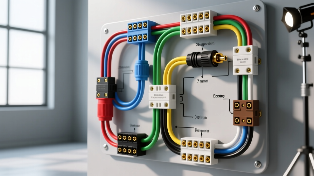
Understanding the RVIA 7-Way Flat Blade Standard
When automotive technicians and RV owners reference a 7 way trailer plug wiring diagram, they are typically dealing with the RVIA (Recreation Vehicle Industry Association) flat blade connector. It is critical not to confuse this with the SAE J560 7-way round pin connector, which is strictly reserved for heavy-duty commercial air-brake trucks and operates on a 24V system. The RVIA 7-way flat blade operates on a 12V DC negative-ground system and integrates lighting, auxiliary power, and electric trailer brakes into a single weather-sealed housing.
Troubleshooting a 7-way system requires a systematic approach. Jumping straight to replacing the trailer plug without verifying the tow vehicle's socket output or the trailer's ground integrity leads to misdiagnosed components and blown fuses. This guide provides a step-by-step diagnostic flow to isolate electrical faults using a digital multimeter (DMM) and a systematic elimination process.
Master Reference: 7-Way Pinout and AWG Specifications
Before beginning the troubleshooting flow, verify that the trailer harness is built to the correct American Wire Gauge (AWG) specifications. A common failure mode in aftermarket harnesses is the use of 14 AWG wire for high-draw circuits, leading to severe voltage drop and melted connector pins.
| Pin Position (Clock Face) | Function | Standard Wire Color | Minimum AWG | Max Continuous Draw |
|---|---|---|---|---|
| Center / Ground | Chassis Ground | White | 8 AWG | 40A+ |
| 1:00 (Top Left) | 12V Auxiliary Power | Black | 10 AWG | 30A |
| 3:00 (Right) | Right Turn / Stop | Brown | 12 AWG | 10A |
| 5:00 (Bottom Right) | Electric Brakes | Blue | 10 AWG | 15A - 20A |
| 7:00 (Bottom Left) | Tail / Running Lights | Green | 12 AWG | 15A |
| 9:00 (Left) | Left Turn / Stop | Red | 12 AWG | 10A |
| 11:00 (Top Right) | Reverse Lights / Aux | Yellow | 12 AWG | 10A |
Phase 1: Vehicle-Side Socket Verification (Baseline Test)
Never connect the trailer until the tow vehicle's socket has been verified. You must establish a known-good baseline.
- Visual Inspection: Check the vehicle socket for green/white galvanic corrosion or pushed-back pins. If the brass pins are recessed, they will not make contact with the trailer plug blades.
- DMM Setup: Set your digital multimeter to DC Volts (20V scale).
- Ground Verification: Place the black probe on a clean, bare metal point on the truck chassis (not the socket housing). Insert the red probe into the White (Ground) pin cavity. The reading must be less than 0.1V. If higher, the vehicle's ground wire from the harness to the chassis is compromised.
- Power Pin Testing: Move the red probe to the Black (12V Aux) pin. You should read 12.2V to 12.6V with the engine off, and 13.8V to 14.4V with the engine running. If you read 0V, check the under-hood fuse panel for the 'Trailer Aux' or 'BATT' fuse, often a 30A or 40A maxi-fuse.
- Signal Testing: Have an assistant activate the turn signals and brake pedal while you probe the Red, Brown, and Green pins to verify PWM or 12V pulse signals from the vehicle's body control module (BCM).
Phase 2: Trailer-Side Harness Continuity and Isolation
If Phase 1 passes, the fault lies in the trailer harness, the plug, or the trailer's grounding points.
- Disconnect and Isolate: Unplug the trailer. Set the DMM to Ohms/Continuity.
- Ground Continuity: Place one probe on the White pin of the trailer plug and the other on the bare metal trailer frame near the axle. Resistance must be below 0.5 ohms. If it reads OL (Open Loop), the trailer's main ground ring terminal is rusted or detached.
- Short-to-Ground Check: Keep the black probe on the trailer frame. Use the red probe to test the Blue (Brakes), Red (Left), and Brown (Right) pins. You should read OL. If you read low resistance, the harness insulation is chafed against the steel frame, causing a dead short that will blow the tow vehicle's fuses upon connection.
Phase 3: Symptom-Cause-Fix Decision Tree
Use this decision tree to diagnose specific real-world failure modes based on the 7 way trailer plug wiring diagram.
Symptom A: Electric Brakes Lock Up or Draw Excessive Current
- Potential Cause 1: Blue wire (Pin 5) shorted to 12V Black wire (Pin 1) inside the molded plug head due to water intrusion and corrosion bridging the gap.
- Fix: Cut off the molded plug, strip back the loom, and install a new hardwired pigtail using heat-shrink butt connectors. Apply dielectric grease to the new pins.
- Potential Cause 2: Brake controller gain set too high, or the manual override switch is stuck in the ON position inside the cab.
- Fix: Recalibrate the proportional brake controller (e.g., Tekonsha P3 or Redarc Tow-Pro) according to the manufacturer's loaded-trailer calibration sequence.
Symptom B: Running Lights Blow Fuses or Dim When Brakes Are Applied
- Root Cause: This is the classic 'Ground Backfeed' syndrome. When the brake lights (high current) and running lights (medium current) are activated simultaneously, the White ground wire cannot handle the return amperage due to high resistance at the trailer frame ground.
- The Physics: The current seeks an alternate path to ground, backfeeding through the turn signal filaments or the 12V auxiliary circuit.
- Fix: Upgrade the trailer's main ground wire to 8 AWG. Scrape away all paint, powder coating, and rust from the trailer tongue where the ground ring terminal attaches. Use a star washer to bite into the bare steel, and coat with battery terminal protector spray.
Symptom C: Left Turn Signal Activates Right Side Marker Lights
- Root Cause: A short circuit between the Red wire (Left Turn) and Brown wire (Right Turn) somewhere in the harness loom, typically where the harness rubs against the A-frame or suspension leaf springs.
- Fix: Perform a 'wiggle test' while monitoring continuity between the Red and Brown pins at the disconnected plug. Once the short is localized, repair the loom using adhesive-lined marine-grade heat shrink (3M or equivalent) to prevent future moisture wicking.
Advanced Diagnostics: Voltage Drop and Galvanic Corrosion
For intermittent issues that only occur while driving over rough terrain, static continuity tests are insufficient. You must perform a dynamic voltage drop test.
Connect the trailer to the vehicle. Back-probe the 12V Auxiliary (Black) pin at the trailer plug while the trailer's interior lights or breakaway battery charger is drawing current. Place the positive DMM probe on the back of the trailer plug pin, and the negative probe directly on the vehicle's alternator positive terminal. A voltage drop greater than 0.5V indicates excessive resistance in the tow vehicle's wiring, the socket contacts, or the trailer plug contacts.
Furthermore, inspect for galvanic corrosion. The interaction between the copper wiring, brass pins, and aluminum or steel trailer frames in the presence of road salt creates a battery effect that eats away at the metal. Always use a high-quality silicone-based dielectric grease on the 7-way pins, but never pack the entire socket cavity, as this can cause hydraulic lock and prevent the pins from seating fully.
Authoritative References
- etrailer.com: Complete Trailer Wiring FAQ and Diagrams - Industry standard reference for RVIA pinouts and harness routing.
- SAE International J560 Standard - Reference for heavy-duty 7-way round pin configurations (to differentiate from RV flat blade).
- Tekonsha Brake Controller Troubleshooting Guide - OEM diagnostic flows for electric brake circuit faults and PWM signal verification.