Understanding the SAE J286 7-Way RV Blade Standard
When towing heavy loads exceeding 3,000 pounds, electric trailer brakes are not just a recommendation; they are a critical safety requirement and often a legal mandate. To properly command these brakes, the tow vehicle and trailer must communicate seamlessly through a standardized connector. The 7-way RV blade connector, governed by the SAE International J286 standard, is the universal benchmark for light-duty and medium-duty towing in North America. This guide provides a complete trailer wiring diagram for electric brakes, walking you through every pin, wire gauge requirement, and routing protocol necessary for a fail-safe installation.
Unlike standard 4-pin flat connectors that only handle basic lighting, the 7-pin configuration dedicates specific, heavy-gauge circuits exclusively for brake actuation, auxiliary 12V power, and reverse lockout solenoids. A flawed installation here doesn't just result in a blown fuse; it can lead to catastrophic brake failure, melted harnesses, or uncommanded trailer acceleration. Below, we dissect the anatomy of the 7-pin system from the tow vehicle's brake controller to the trailer's backing plates.
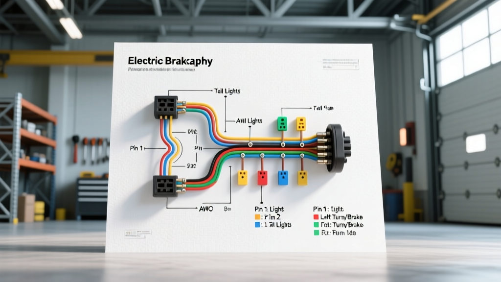
Complete 7-Pin Trailer Wiring Diagram & Pinout Chart
The physical layout of the 7-way RV blade places the heavy-duty power and ground circuits at the bottom of the connector to prevent water ingress and short-circuiting in the event of debris impact. Below is the definitive pinout reference for both the vehicle-side socket and the trailer-side plug.
| Pin Position | Function | Standard Wire Color | Minimum AWG | Max Amperage / Notes |
|---|---|---|---|---|
| Pin 1 (Bottom Center) | System Ground (White) | White | 10 AWG | 40A+ Continuous. Must ground to clean chassis. |
| Pin 2 (Top Right) | Electric Brakes (Blue) | Blue | 10 AWG | 20A-30A peak. Carries PWM or DC from controller. |
| Pin 3 (Bottom Left) | Tail / Running Lights | Brown | 16 AWG | 10A. Fused at 15A on tow vehicle. |
| Pin 4 (Top Left) | Left Turn / Stop | Yellow | 16 AWG | 10A. Combined stop/turn signal. |
| Pin 5 (Center Right) | 12V Aux / Battery Charge | Black | 10 AWG | 30A-40A. Requires 40A auto-reset breaker. |
| Pin 6 (Top Center) | Right Turn / Stop | Green | 16 AWG | 10A. Combined stop/turn signal. |
| Pin 7 (Center Left) | Reverse Lights / Lockout | Red or Purple | 16 AWG | 10A. Used for surge brake reverse lockout solenoids. |
Tow Vehicle Side: Brake Controller Integration Walkthrough
The heart of the electric brake system on the tow vehicle is the proportional brake controller (e.g., Tekonsha Prodigy P3 or Curt Echo). According to Tekonsha's official installation guidelines, a proportional controller requires four distinct wire connections to function correctly and safely interface with the 7-pin socket.
The Four Brake Controller Wires
- White (Ground): Must be routed directly to the vehicle's negative battery terminal or a verified, unpainted chassis ground. Do not rely on sheet metal screws into the cab floor; use a star washer and ring terminal bolted to a heavy frame rail.
- Black (12V Power Input): This feeds the controller and the trailer brakes. It must be run directly to the positive battery terminal. Critical Spec: You must install a 30-amp or 40-amp auto-reset circuit breaker within 18 inches of the battery positive post to protect the 10 AWG wire from thermal events.
- Red (Stoplight Switch Input): This wire tells the controller when you are pressing the brake pedal. It must be spliced into the 'cold' side of the vehicle's brake light switch (the wire that only shows 12V when the pedal is depressed). Splicing into the wrong circuit, such as the cruise control cancel switch, will cause erratic brake behavior.
- Blue (Brake Output): This is the high-current output wire that travels to Pin 2 of the 7-way connector. It carries the modulated voltage to the trailer's brake magnets.
Trailer Side: Junction Box and Breakaway Switch Routing
On the trailer side, running individual wires from the 7-way plug all the way to the axles is a recipe for voltage drop and physical damage. Professional installations utilize a Trailer Wiring Junction Box mounted near the tongue. The 7-way pigtail terminates inside this weather-sealed box, and heavier, jacketed 7-conductor cable is run back to the axles.
Integrating the Breakaway Switch
Federal DOT regulations require trailers with electric brakes to have a breakaway system. If the trailer disconnects from the hitch, a lanyard pulls a pin from a normally-closed switch, applying full 12V battery power directly to the brake magnets to stop the runaway trailer. Here is how to wire it into the junction box:
- Run a dedicated 10 AWG positive lead from the trailer's breakaway battery to one terminal of the breakaway switch.
- Run a second 10 AWG wire from the other terminal of the switch and splice it directly into the Blue (Pin 2) electric brake wire on the trailer side of the junction box.
- Warning: Never wire the breakaway switch into the brake controller output or the tow vehicle's power feed. It must be an independent circuit powered solely by the trailer-mounted battery.
Advanced Diagnostics: Testing Electric Brake Circuits
When troubleshooting a trailer wiring diagram for electric brakes, visual inspection is rarely enough. You must use a digital multimeter (DMM) to verify circuit integrity. A common failure mode is 'ground backfeed,' where a corroded Pin 1 (White) forces the lighting circuits to seek a ground through the brake magnets, causing lights to dim when brakes are applied.
Voltage Drop Testing on the Blue Wire
To test the health of the electric brake circuit, perform a voltage drop test under load. Set your DMM to DC Volts. Place the red probe on the Blue wire output at the brake controller, and the black probe on the Blue wire at the trailer's furthest axle brake magnet. Have an assistant apply the manual override lever on the controller to maximum gain. A healthy 10 AWG circuit should show a voltage drop of less than 0.5 volts. If the drop exceeds 1.0 volts, you have high resistance—likely due to undersized wire, corroded butt connectors, or a failing 7-pin plug.
Testing Proportional vs. Time-Delayed Controllers
If you are diagnosing a proportional controller, note that the Blue wire outputs a Pulse Width Modulated (PWM) signal, not a steady DC voltage. A standard multimeter may read erratic voltages between 4V and 11V while driving. To properly read a PWM signal, you must use an oscilloscope or a multimeter with a specific PWM duty-cycle function. Alternatively, use a dedicated etrailer-approved brake controller tester that features an LED bar graph designed to interpret the PWM pulses into a readable braking force metric.
Environmental Protection and Wire Routing Best Practices
The undercarriage of a trailer is a hostile environment characterized by road salt, high-pressure water, and extreme temperature fluctuations. To ensure your electric brake wiring survives, all 10 AWG and 16 AWG wires must be encased in split-loom tubing or braided nylon sleeving. Where the harness passes through any metal crossmembers or the trailer tongue, you must use rubber grommets to prevent the metal from slicing through the wire insulation, which would immediately short the blue brake wire to the chassis.
Finally, every single connection made outside the junction box must be sealed. Avoid standard vinyl electrical tape, which unspools in high heat and moisture. Instead, use adhesive-lined heat shrink butt connectors and coat all 7-way plug terminals with a high-quality dielectric grease to prevent copper oxidation and galvanic corrosion between the brass pins and the socket contacts.