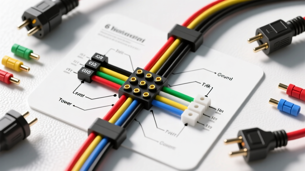
Understanding the 6 Pin Voltage Regulator Wiring Diagram for Trailer Applications
When towing heavy-duty 5th wheels, car haulers, or custom toy haulers, the standard 7-way RV connector often falls short of modern electrical demands. The 12V auxiliary pin (Pin 4) on a standard trailer plug is notorious for severe voltage drop over 25-foot umbilical runs, leading to undercharged breakaway batteries and sulfated deep-cycle house banks. To solve this, many custom trailer builders and heavy-duty tow vehicle upfitters install a secondary charging system or a trailer-mounted generator managed by an external regulator.
This beginner-friendly guide breaks down the 6 pin voltage regulator wiring diagram, translating complex automotive electrical theory into actionable steps. Whether you are upgrading your tow vehicle's alternator to handle electric trailer brakes and auxiliary charging, or wiring a standalone trailer generator, understanding how to properly route the Field, Sense, and Battery circuits is critical for a safe, fire-free installation.
Why Use an External 6-Pin Regulator for Trailer Charging?
Modern internal voltage regulators (built into the alternator) rely on local voltage readings. In a trailer application, reading voltage at the alternator's output terminal doesn't account for the 1.5 to 2.0 volts lost across the tow vehicle's wiring harness, the 7-pin connector, and the trailer's internal distribution block.
A 6-pin external regulator solves this by utilizing a dedicated Remote Sense wire. By running this sense wire directly to the trailer's battery bus, the regulator uses Pulse Width Modulation (PWM) to push the alternator harder, compensating for the voltage drop across the trailer harness and ensuring your trailer's lithium or AGM batteries receive the exact bulk/absorption voltage they require.
Decoding the 6-Pin Connector Pinout
Before cutting any wire, you must identify the terminals on your specific regulator housing. While manufacturers like Wells, Motorcraft, and Delco Remy have slight variations, the industry-standard 6-pin external regulator follows this fundamental layout:
- Terminal 1: IGN (Ignition / Excite) - Provides the initial 12V+ signal to 'wake up' the regulator and alternator when the tow vehicle is running.
- Terminal 2: GND (Ground) - The critical reference ground for the regulator's internal logic board.
- Terminal 3: FLD (Field) - Sends the PWM ground-path signal to the alternator's rotor brushes to control magnetic field strength.
- Terminal 4: LAMP (Indicator) - Drives the dash charge-indicator light and provides a secondary excitation path.
- Terminal 5: SENSE (Remote Voltage) - The most important wire for trailer applications; reads actual voltage at the destination battery bank.
- Terminal 6: BAT (Battery Feed) - Provides main 12V+ power to the regulator's internal switching transistors.
Wire Gauge and Routing Specifications
Using the wrong wire gauge in a high-amperage trailer charging system is a leading cause of melted 7-pin connectors and electrical fires. Always use automotive-grade cross-linked polyethylene wire (TXL or GXL), which resists heat, abrasion, and battery acid far better than standard PVC wire.
| Terminal | Function | Recommended AWG | Wire Color Code | Trailer Routing Notes |
|---|---|---|---|---|
| BAT (6) | Main Power Feed | 10 AWG | Red | Must be fused within 8 inches of the battery source. |
| FLD (3) | Alternator Field | 14 AWG | Green | Keep away from high-voltage AC ignition wires to prevent noise. |
| SENSE (5) | Remote Voltage Read | 16 AWG | White | Run through trailer umbilical directly to house battery positive. |
| IGN (1) | Switched 12V+ | 14 AWG | Purple | Tie to tow vehicle ignition or trailer generator start relay. |
| LAMP (4) | Charge Indicator | 16 AWG | Yellow | Requires a 194 bulb or LED resistor to complete the circuit. |
| GND (2) | Logic Ground | 12 AWG | Black | Use a star washer on bare chassis metal; never use a painted surface. |
Step-by-Step Installation Guide for Beginners
Follow these steps to wire your 6 pin voltage regulator wiring diagram safely and effectively. For deeper insights into trailer connector standards and heavy-duty routing, reference the wiring guides at etrailer's FAQ and the alternator tech articles at Madelectrical.
Step 1: Mount the Regulator for Heat Dissipation
External regulators handle massive amounts of heat as they pulse the alternator's field circuit. Mount the regulator flat against the firewall or a metal bracket in the engine bay (or inside a ventilated trailer generator enclosure). Use thermal paste or a thermal pad between the regulator's aluminum backplate and the mounting surface. Never mount it near exhaust manifolds.
Step 2: Establish a Bulletproof Ground
The GND (Pin 2) wire dictates the accuracy of the entire system. If the regulator has a poor ground, it will read a false low voltage and overcharge your trailer batteries, potentially boiling the electrolyte or triggering a lithium BMS shutdown. Scrape away all paint and primer, use a stainless steel star washer, and torque the ground bolt to the manufacturer's specification. Coat the terminal in dielectric grease after tightening.
Step 3: Route the Remote Sense Wire (The Trailer Secret)
Run the 16 AWG White SENSE wire (Pin 5) from the regulator, through the tow vehicle's firewall, down the chassis, and into the 7-way plug (using an auxiliary pin if building a custom 8-pin or 9-pin heavy-duty connector, or tying into a dedicated trailer charge line). At the trailer end, connect this wire directly to the positive bus bar of the trailer's battery bank. Pro Tip: Install an inline 5A AGC fuse on the sense wire near the battery to protect the regulator's internal circuitry in the event of a short.
Step 4: Wire the Field and Battery Circuits
Connect the 10 AWG Red BAT wire to the main alternator output stud or the positive battery terminal. Connect the 14 AWG Green FLD wire to the alternator's field terminal. On older Delco 10SI or 12SI alternators commonly used in budget trailer generator builds, this is typically the 'F' spade terminal. Ensure all connections are crimped using a ratcheting crimper and sealed with adhesive-lined marine heat shrink.
Troubleshooting Common Trailer Charging Faults
Even with a perfect 6 pin voltage regulator wiring diagram, environmental factors on the road can cause issues. Use this diagnostic tree to solve common problems:
- Symptom: Trailer batteries are boiling / Overcharging (15.5V+).
Cause: The SENSE wire is broken or disconnected. The regulator is defaulting to reading voltage at its local BAT terminal, which is lower than the battery voltage due to wire resistance, causing it to overcompensate.
Fix: Check the 5A inline fuse on the SENSE wire and test for continuity from the regulator Pin 5 to the trailer battery positive. - Symptom: Alternator whines and trailer lights dim at idle.
Cause: Undersized ground wire or poor chassis ground on the alternator/regulator.
Fix: Upgrade the alternator ground strap to 8 AWG and verify the regulator GND pin has less than 0.05V of resistance to the battery negative. - Symptom: Regulator gets too hot to touch.
Cause: The alternator field circuit is drawing too many amps, often due to worn alternator brushes or a shorted rotor.
Fix: Measure the resistance across the alternator's FLD and ground terminals. It should read between 3 to 5 ohms. If it reads near 0 ohms, replace the alternator rotor.
Final Thoughts on Trailer Electrical Safety
Upgrading your trailer charging system with a 6-pin external regulator is one of the most effective ways to ensure your electric brake breakaway systems and auxiliary house batteries remain fully charged on long hauls. By respecting wire gauge limits, utilizing automotive-grade GXL wire, and properly routing the remote sense circuit, you eliminate the voltage drop that plagues standard 7-way RV connectors. Always consult Haynes technical tutorials for vehicle-specific alternator pinouts before tapping into your tow vehicle's factory harness, and always disconnect the negative battery terminals before beginning any high-current wiring project.