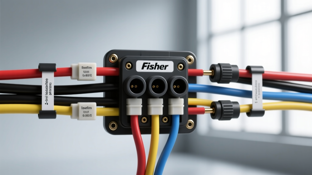
Introduction to Fisher Multiplex & Isolation Module Systems
Understanding modern Fisher plow wiring diagrams requires a fundamental shift from legacy relay-based logic to advanced multiplex communication. Fisher Engineering revolutionized the snow removal industry by transitioning from bulky, corrosion-prone 12-pin relay systems to a streamlined 3-plug multiplex architecture. This system, commonly found on EZ-V and Minute Mount 2 setups, drastically reduces the number of physical wires crossing between the truck and the plow while increasing diagnostic capabilities.
For automotive electrical technicians and fleet upfitters, interpreting these schematics goes far beyond matching wire colors. It requires an understanding of Pulse Width Modulation (PWM) headlight circuits, CAN-bus data lines, and strict voltage drop tolerances. This complete walkthrough dissects the Fisher 3-plug isolation module system, providing actionable routing instructions, pinout configurations, and real-world failure mode diagnostics that you will not find in a standard owner's manual.
The 3-Plug Electrical System Architecture
The contemporary Fisher electrical harness relies on three distinct connection points between the vehicle-side isolation module and the plow-side control module. This separation ensures that high-amperage hydraulic loads do not induce electromagnetic interference (EMI) on sensitive data and lighting circuits.
- Plug A (2-Pin Power/Ground): Handles the massive current draw of the hydraulic motor and provides the main chassis ground reference.
- Plug B (11-Pin Lighting & Control): Carries multiplexed lighting signals, ignition feeds, and joystick data communication.
- Plug C (4-Pin Solenoid/Valve): Routes the pulsed ground signals to the hydraulic manifold valves for lift, lower, and angle functions.
By isolating the high-current motor feed from the logic circuits, Fisher minimizes voltage sag across the lighting module, a common issue in older setups that caused headlights to dim every time the plow was raised.
Pinout & Wire Color Reference Chart (11-Pin Lighting & Control)
The 11-pin connector (Plug B) is the nerve center of the Fisher multiplex system. Below is the standard pinout configuration for late-model EZ-V and Multiplex systems. Always verify with your specific vehicle kit schematic, as OEM integration (e.g., Ford Upfitter vs. GM BCM) can dictate slight variations in the ignition feed routing.
| Pin # | Wire Color | Function / Signal | AWG Size | Diagnostic Notes |
|---|---|---|---|---|
| 1 | Black/White | Left Turn / Stop | 16 AWG | Verify continuity to truck BCM output. |
| 2 | Brown | Running / Marker Lights | 16 AWG | Test for 12V+ with parking lights ON. |
| 3 | Green/White | Right Turn / Stop | 16 AWG | Check for cross-talk with Pin 1. |
| 4 | Black | Logic Ground | 12 AWG | Critical: Voltage drop must be < 0.1V. |
| 5 | Blue | High Beam Feed | 16 AWG | Requires PWM filter on modern GM trucks. |
| 6 | Red/Black | 12V Ignition Feed | 14 AWG | Fused at 10A. Wakes up the isolation module. |
| 7 | White | Low Beam Feed | 16 AWG | Primary plow headlight power source. |
| 8 | Purple | Joystick Data (TX/RX) | 18 AWG | Multiplex serial data. Do not splice. |
| 9 | Yellow | Auxiliary / Strobe | 16 AWG | Often used for work lights or beacon triggers. |
| 10 | Green | Plow Side Module Status | 18 AWG | Handshake signal for module synchronization. |
| 11 | Orange | Diagnostic Feedback | 18 AWG | Used for reading flash codes via controller. |
Step-by-Step Harness Routing & Module Wiring
Phase 1: Power & Ground (The 2-Pin Harness)
The most common cause of premature hydraulic pump failure and solenoid burnout is inadequate power delivery. The main power cable must be 2 AWG or 1/0 AWG stranded copper, routed directly from the positive battery terminal to the plow solenoid. Do not route this through the factory fuse block. Install a 150A or 200A MEGA fuse within 18 inches of the battery positive terminal to comply with NTEA upfitter safety guidelines.
The ground cable is equally critical. It must terminate on a clean, bare-metal point on the engine block or chassis frame. Use a 3/8-inch ring terminal, secure it with a Grade 8 bolt, and torque it to 15-20 ft-lbs. Coat the termination with dielectric grease only *after* torqueing to prevent micro-corrosion that leads to resistance spikes.
Phase 2: Lighting Isolation & PWM Adaptation
Modern vehicles, particularly 2019+ GM Silverados and Ford Super Duties, utilize Pulse Width Modulation (PWM) to control headlight circuits, reducing the voltage to extend bulb life. The Fisher isolation module expects a steady 12V+ DC signal. If you connect a PWM headlight circuit directly to the Fisher harness (Pins 5 and 7), the truck's Body Control Module (BCM) will detect an abnormal current draw and shut down the circuit, resulting in dead plow lights.
To resolve this, you must install a Fisher PWM adapter/filter module inline with the headlight feeds. This module reads the PWM duty cycle and triggers an internal relay to supply a clean, constant 12V+ from the battery to the plow headlights. When routing the HB4, HB5, or H11 adapter pigtails, ensure they are secured away from exhaust manifolds using UV-resistant zip ties and split-loom tubing.
Phase 3: Firewall Routing & Joystick Data
Routing the 11-pin and 4-pin harnesses through the firewall requires extreme care. Never drill blindly through the firewall; use an existing OEM grommet (often located behind the driver's side kick panel or near the steering column). If you must drill, use a step-bit to create a clean hole and install a rubber firewall grommet. Apply a liberal amount of silicone sealant around the grommet edge to prevent water and carbon monoxide intrusion into the cab.
The joystick data line (Pin 8, Purple) carries high-speed multiplex serial data. Unlike standard DC power wires, this data line is highly susceptible to Electromagnetic Interference (EMI). According to SAE J1113 EMC standards, data lines should be routed at least 12 inches away from high-current alternator cables, ignition coils, and aftermarket CB radio power feeds to prevent packet loss, which manifests as joystick lag or unresponsive plow movements.
Common Failure Modes & Multimeter Diagnostics
When troubleshooting Fisher plow wiring diagrams in the field, rely on your multimeter and the controller's diagnostic flash codes rather than guessing. Here are the most frequent failure modes and how to isolate them:
- Symptom: Controller displays 3 flashing lights.
Cause: Lost communication between the cab controller and the under-hood isolation module.
Fix: Check Pin 8 (Purple) and Pin 4 (Black/Ground) at the 11-pin connector. Verify the 10A ignition fuse on Pin 6 is intact. Clean the 11-pin connector contacts and apply Nyogel 760G dielectric grease to prevent fretting corrosion. - Symptom: Plow headlights flicker or truck headlights shut off when plow is plugged in.
Cause: BCM overload due to missing PWM adapter, or a short in the plow-side headlight harness.
Fix: Unplug the plow-side headlight harness. Turn on the truck lights. If the truck lights stay on, the fault is in the plow harness (check for pinched wires near the A-frame pivot). If the truck lights still shut off, verify the PWM module installation and headlight adapter pinouts. - Symptom: Motor runs slowly or solenoid clicks rapidly under load.
Cause: Severe voltage drop on the 2 AWG power or ground cables.
Fix: Perform a voltage drop test. Place your multimeter probes on the battery positive terminal and the motor-side stud of the solenoid. Have an assistant activate the 'Lift' function. A reading higher than 0.2V indicates high resistance (corroded terminal, loose crimp, or undersized wire). Repeat the test on the ground side.
Termination Best Practices & Corrosion Mitigation
The harsh environment of snow plowing—characterized by brine, magnesium chloride, and extreme temperature cycling—will rapidly destroy poor electrical terminations. Never use solder on high-flex areas like the plow-to-truck umbilical harness; solder wicks into the wire strands, creating a rigid point that will eventually snap under vibration and cold-weather stiffness.
Instead, use adhesive-lined marine-grade heat shrink crimp terminals. When terminating the 2 AWG battery cables, use a hydraulic or heavy-duty ratcheting crimper to ensure a gas-tight connection. After crimping, apply heat until the adhesive sealant oozes from the edges of the shrink tube. Finally, coat all exposed multiplex pins and solenoid spade connectors with a lithium-based or synthetic dielectric grease specifically formulated for automotive electronics to displace moisture and prevent galvanic corrosion between dissimilar metals.
Authoritative References
For vehicle-specific schematics and module programming updates, always consult the official manufacturer documentation and industry standards: