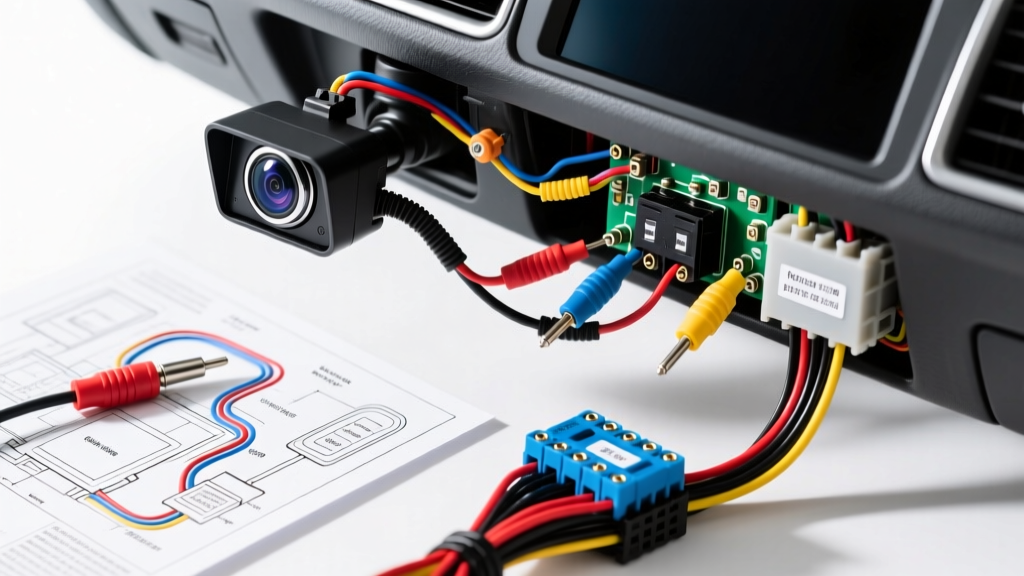
Introduction to the Back Up Camera Install Circuit
Executing a flawless back up camera install requires more than simply routing a video cable from the trunk to the dash. Modern vehicle electrical systems demand a precise understanding of voltage tolerances, signal shielding, and data-bus interference. A standard aftermarket camera system operates on four distinct circuit branches: the 12V switched power feed, the chassis ground, the reverse trigger signal for the head unit, and the shielded RCA video transmission line. This complete wiring diagram walkthrough dissects the anatomy of a professional-grade back up camera install, highlighting the exact wire gauges, pin configurations, and CAN-bus bypass strategies necessary to prevent flickering, alternator whine, and head unit reboots.
Core Wiring Diagram & Pinout Configuration
Before stripping any wires, map the circuit topology. The camera itself typically features a 4-pin aviation connector or a molded pigtail that breaks out into power, ground, and video. The head unit requires a dedicated reverse trigger input to switch the display matrix from standard infotainment to the camera feed. Below is the standard pinout and wire specification chart for a universal NTSC/PAL backup camera system integrated into a modern double-DIN receiver.
| Circuit Function | Wire Color (Typical) | AWG Rating | Connection Point | Insulation Type |
|---|---|---|---|---|
| Camera 12V Power | Red | 18 AWG | Reverse Lamp (+) or Relay 87 | TXL / GXL Cross-Linked |
| Camera Chassis Ground | Black | 18 AWG | Chassis Bolt / Reverse Lamp (-) | TXL / GXL Cross-Linked |
| Video Signal | RCA Center Pin | 24 AWG Coax | Head Unit RCA Input | Shielded Coaxial |
| Video Ground | RCA Shield | Braided Copper | Head Unit RCA Outer Ring | Shielded Coaxial |
| Head Unit Reverse Trigger | Purple / White | 22 AWG | Reverse Lamp (+) or Relay 87 | Standard PVC / TXL |
Step-by-Step Power and Ground Routing Specifications
The most common point of failure in a back up camera install is voltage drop at the camera pigtail. While the camera draws minimal current (typically 120mA to 250mA), running 25 feet of substandard wire can drop the voltage below the 10.5V threshold required by the internal CMOS sensor and IR illuminators.
Power Feed Routing
Always use 18 AWG stranded copper wire with TXL (Thin-wall Cross-linked) or GXL insulation. These insulation types withstand engine bay and trunk transit temperatures up to 125°C, unlike standard PVC primary wire which becomes brittle and cracks under thermal cycling. When tapping the reverse light circuit at the rear of the vehicle, avoid 3M Scotchlok tap connectors. These puncture the wire jacket, exposing the copper strands to galvanic corrosion and moisture ingress. Instead, use Posi-Tap connectors or, ideally, strip the harness, solder the 18 AWG jumper, and seal it with adhesive-lined dual-wall heat shrink tubing.
Chassis Grounding Protocol
If a dedicated ground wire is not available at the taillight housing, you must establish a chassis ground. Locate an M6 or M8 structural bolt in the trunk pan. Remove the bolt, sand the contact area down to bare, unpainted metal using 120-grit sandpaper, and crimp an 18 AWG closed-loop ring terminal. Reinstall the bolt and torque it to 10 Nm (7.4 lb-ft) to ensure low-resistance continuity. Apply a dab of dielectric grease over the terminal to prevent oxidation. Verify the ground with a multimeter; resistance between the camera ground wire and the vehicle battery negative terminal must read less than 0.05 ohms.
Tapping the Reverse Trigger & Bypassing CAN-Bus PWM
Modern vehicles (2015 and newer, including the F-150, Ram 1500, and most European platforms) utilize a Body Control Module (BCM) to manage exterior lighting. The BCM does not output a clean 12V DC signal to the reverse lamps; instead, it uses Pulse Width Modulation (PWM) to monitor bulb health. If you tap this PWM signal directly for your back up camera install, the camera will flicker, and the head unit's trigger circuit will rapidly cycle on and off, potentially corrupting the receiver's boot sequence.
Diagnosing PWM Signals
Set your digital multimeter to DC Voltage and probe the reverse lamp positive wire while the vehicle is in reverse. If the reading fluctuates between 9V and 12V, or sits at a steady but low 10.5V, you are reading a PWM square wave. To confirm, an oscilloscope will reveal a 50Hz to 400Hz square wave rather than a flat DC line.
The Relay Bypass Solution
To secure a clean 12V DC feed for both the camera power and the head unit trigger, install a standard 30A Bosch-style automotive mini-relay in the trunk.
- Pin 86 (Coil +): Connect to the vehicle's PWM reverse lamp positive wire.
- Pin 85 (Coil -): Connect to a solid chassis ground.
- Pin 30 (Common): Connect to a fused 12V constant or 12V ignition source from a nearby harness or fuse tap.
- Pin 87 (Normally Open): Connect to the camera's Red power wire AND the head unit's Purple/White reverse trigger wire.
When the BCM pulses the reverse lights, the relay coil energizes, closing the contact between Pin 30 and Pin 87. This delivers a flawless, high-amperage 12V DC signal to the camera and head unit, entirely isolating your aftermarket gear from the vehicle's sensitive CAN-bus network. For detailed OEM wiring schematics to locate ignition sources, consult resources like AllDataDIY.
RCA Video Signal Routing & Shielding
The video signal transmitted via the RCA cable is a low-voltage analog waveform (typically 1V peak-to-peak for NTSC composite video). This makes it highly susceptible to Electromagnetic Interference (EMI). According to SAE J1113 standards for electromagnetic compatibility, low-voltage signal lines must be physically separated from high-current switching cables.
Routing Best Practices
When routing the RCA extension cable from the trunk to the dash, maintain a minimum 6-inch separation from 4-AWG or 0-AWG amplifier power wires, fuel pump feed lines, and ignition coil harnesses. If the RCA cable must cross a high-current power wire, ensure it crosses at a strict 90-degree angle to minimize inductive coupling. Never zip-tie the RCA cable parallel to the vehicle's main wiring loom, as the CAN-bus data lines (CAN-H and CAN-L) operate on high-frequency switching that can induce rolling horizontal bars on the camera display.
If EMI is unavoidable due to cabin constraints, install a clamp-on ferrite bead choke near the head unit end of the RCA cable to attenuate high-frequency radio frequency interference (RFI). Additionally, wrap the RCA connections at the camera pigtail in self-amalgamating silicone tape to prevent moisture from wicking into the coaxial shielding via capillary action.
Common Failure Modes & Multimeter Diagnostics
Even with a meticulous back up camera install, environmental factors and component degradation can cause faults. The Mobile Electronics Certification Program (MECP) recommends a systematic diagnostic approach before removing interior trim panels. Use the following decision tree and diagnostic table to isolate faults.
| Symptom | Probable Cause | Multimeter Diagnostic Test | Corrective Action |
|---|---|---|---|
| Image flickers rapidly | PWM interference on power feed | Measure DC Voltage at camera pigtail; look for fluctuations. | Install 12V relay bypass or PWM filter capacitor (1000µF 16V). |
| Rolling horizontal bars | Ground loop or EMI induction | Check AC Voltage on RCA shield; verify chassis ground resistance. | Re-route RCA away from amp power; add ground loop isolator. |
| No image, blue/black screen | Head unit trigger not receiving 12V | Measure DC Voltage at head unit Purple/White wire in reverse. | Repair broken trigger wire; check inline fuse. |
| Image only appears when braking | Tapped brake light instead of reverse | Verify 12V presence with transmission in Park + Brake pressed. | Relocate tap to dedicated reverse lamp circuit. |
| Dark/muddy image at night | Voltage drop starving IR illuminators | Measure voltage at camera while IR LEDs are active (night). | Upgrade to 16 AWG power feed or clean corroded ground point. |
Advanced PWM Filtering Alternative
If space constraints prohibit the use of a mechanical relay, you can build a solid-state PWM filter for the trigger wire. Solder a 1N4007 rectifier diode in series with the reverse lamp positive wire (band facing away from the lamp), followed by a 1000µF 16V electrolytic capacitor bridging the output side of the diode to ground. The diode blocks the negative duty cycle of the PWM wave, while the capacitor charges during the positive pulse and discharges during the off-cycle, outputting a smoothed, near-constant 11.8V DC signal capable of triggering the head unit reliably.
By adhering to these exact wire specifications, routing protocols, and CAN-bus isolation techniques, your back up camera install will meet OEM-level reliability standards, ensuring crisp video and seamless integration for the life of the vehicle.