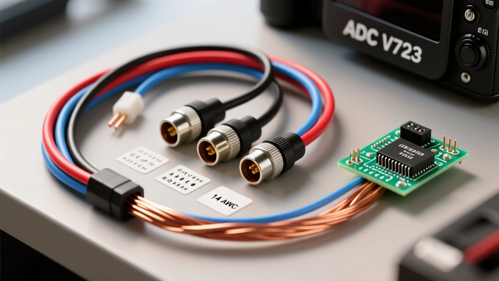
ADC V723 Architecture and Heavy-Duty Integration
The ADC V723 camera system represents a commercial-grade standard for fleet, RV, and heavy-towing applications. Unlike consumer-grade dash cams that rely on flimsy RCA connectors and 12V cigarette lighter taps, the V723 utilizes a robust 4-pin GX16 aviation connector and requires a dedicated, stabilized DC power supply. Performing a proper ADC V723 camera install demands a thorough understanding of automotive electrical networks, specifically regarding Pulse Width Modulation (PWM) interference, Electromagnetic Interference (EMI) shielding, and voltage drop over long cable runs.
Standard installation guides often fail to address the complexities of modern CAN-bus multiplexed networks found in 2015+ Ford Super Duty, Ram 2500/3500, and GM HD trucks. Tapping directly into a PWM-controlled reverse light circuit will cause the V723 monitor to strobe, reboot, or display a 'No Signal' error. This advanced technical deep dive will walk you through the exact pinouts, relay isolation harnesses, and signal integrity protocols required for a flawless, OEM-grade integration.
GX16 4-Pin Aviation Connector Pinout Matrix
The physical interface between the ADC V723 camera head and the main monitoring unit is a 4-pin GX16 aviation connector. This threaded, IP67-rated connector ensures a secure mechanical and electrical bond, even under high-vibration conditions. When repairing or extending the factory harness, you must adhere to the IPC/WHMA-A-620 Requirements for Cable and Wire Harness Assemblies to maintain the coaxial shielding integrity.
| Pin Number | Function | Wire Color (Standard) | Wire Gauge / Type | Signal Specification |
|---|---|---|---|---|
| 1 | VCC (Power) | Red | 18 AWG Stranded (SAE J1128 GXL) | 12V - 24V DC, Max 1.5A |
| 2 | Audio / Trigger | White | 18 AWG Stranded | 12V Trigger or Line-Level Audio |
| 3 | Video Signal | Yellow (Coaxial Core) | 75-Ohm Coaxial (RG59 equiv.) | 1.0V p-p CVBS (NTSC/PAL) |
| 4 | Ground | Black | 18 AWG Stranded | Chassis / Signal Return |
Pro-Tip: When mating the GX16 connector, apply a thin layer of dielectric grease to the rubber O-ring and threading. Tighten the locking collar by hand, then use a spanner wrench for an additional 1/8th turn. Do not overtighten, as this will deform the O-ring and compromise the IP67 moisture seal, leading to internal lens condensation.
Power Delivery: Overcoming PWM Interference
Modern vehicles utilize PWM to control lighting circuits, including reverse lamps. Instead of a steady 12V, the Body Control Module (BCM) pulses the ground or power at high frequencies (often 200Hz - 500Hz) to monitor bulb health and reduce heat. The ADC V723's internal voltage regulator cannot filter these rapid spikes, resulting in erratic camera behavior.
To resolve this, you must install an isolated reverse trigger harness using a standard Bosch-style ISO mini relay and a PWM filter capacitor. This guarantees the camera receives a clean, continuous 12V DC signal.
Building the Isolated Reverse Trigger Harness
You will need a 12V 30A automotive relay, a 1000µF 25V electrolytic capacitor, 14 AWG primary wire for the main power feed, and an inline 5A ATC fuse holder. For the primary wiring, we strictly recommend adhering to the SAE J1128 Low Tension Primary Cable Standard to ensure the wire insulation can withstand under-hood or chassis-routed temperature extremes.
- Main Power Feed: Route a continuous length of 14 AWG red wire directly from the vehicle battery positive terminal to the monitor's main 12V+ input. Install a 5A ATC fuse within 8 inches of the battery terminal.
- Relay Coil (Pins 85 & 86): Connect Pin 86 to the vehicle's reverse light positive wire. Solder the 1000µF capacitor in parallel across Pins 85 and 86 (capacitor positive to Pin 86, negative to Pin 85) to smooth the PWM signal into a steady DC voltage. Connect Pin 85 to a clean chassis ground.
- Relay Contacts (Pins 30 & 87): Connect Pin 30 to the same battery-fed 14 AWG power source (post-fuse). Connect Pin 87 to the V723 monitor's reverse trigger input wire (usually purple or labeled 'BACK').
- Grounding: Ground the monitor's main black wire directly to the battery negative terminal or a dedicated, unpainted chassis grounding stud. Avoid sharing grounds with high-draw accessories like winches or inverters to prevent ground loops.
Signal Integrity: Coaxial Routing and EMI Mitigation
The Composite Video Baseband Signal (CVBS) transmitted on Pin 3 operates at approximately 1.0V peak-to-peak with a 75-ohm impedance. Because the signal voltage is incredibly low, it is highly susceptible to Electromagnetic Interference (EMI) from the vehicle's alternator, ignition coils, and aftermarket RF transmitters.
If the ADC V723 camera install requires extending the factory aviation cable, never use standard 18 AWG stranded wire for the video core. You must use 75-ohm coaxial cable (such as RG59 or specific automotive CCTV coax). Splicing coaxial cable requires heat-shrink solder sleeves to maintain the dielectric barrier. If the braided shield is compromised or improperly grounded at the monitor end, you will experience 'alternator whine' in the audio channel and 'herringbone' interference patterns on the video feed.
Voltage Drop Considerations for Long Wheelbase Vehicles
When routing power to a camera mounted on the rear of a 40-foot motorhome or a 53-foot enclosed trailer, voltage drop becomes a critical factor. The V723 requires a minimum of 10.5V at the camera head to maintain IR illumination and video processing. Using undersized wire will result in the camera shutting down when the IR LEDs engage at night.
| Wire Gauge (AWG) | Total Run Length (Positive + Negative) | Current Draw (IR Active) | Voltage Drop | Resulting Voltage at Camera |
|---|---|---|---|---|
| 18 AWG | 40 Feet | 1.2 Amps | 1.26V | 10.74V (Marginal) |
| 16 AWG | 40 Feet | 1.2 Amps | 0.79V | 11.21V (Acceptable) |
| 14 AWG | 40 Feet | 1.2 Amps | 0.50V | 11.50V (Optimal) |
Note: Calculations assume a baseline alternator output of 12.0V at the source and standard copper conductivity at 75°F. Always upsize your wire gauge if routing through high-temperature zones near exhaust manifolds or EGR coolers.
Diagnostic Decision Tree: V723 Troubleshooting
When an ADC V723 camera install fails to perform as expected, use this systematic diagnostic tree to isolate the fault without replacing expensive components unnecessarily.
- Symptom: Monitor displays 'No Signal' when shifted into reverse.
- Check 1: Measure voltage at Pin 1 and Pin 4 at the camera head with a multimeter. If below 10.5V, you have a voltage drop issue. Upsize the 18 AWG harness to 14 AWG.
- Check 2: Verify the 75-ohm coaxial core (Pin 3) for continuity. A short to the braided shield will collapse the video signal.
- Symptom: Video image scrolls vertically or exhibits rolling horizontal bars.
- Cause: Ground loop. This occurs when the camera chassis ground and the monitor ground are at different electrical potentials.
- Fix: Isolate the camera's metal mounting bracket from the vehicle chassis using nylon shoulder washers. Run the Pin 4 ground wire all the way back to the monitor's dedicated ground point.
- Symptom: Camera image flickers or monitor reboots continuously.
- Cause: Unfiltered PWM signal from the BCM on the reverse trigger wire.
- Fix: Install the isolated relay harness with the 1000µF smoothing capacitor as detailed in the power delivery section.
Authoritative References
For further reading on automotive electrical standards and harness fabrication, consult the following resources: