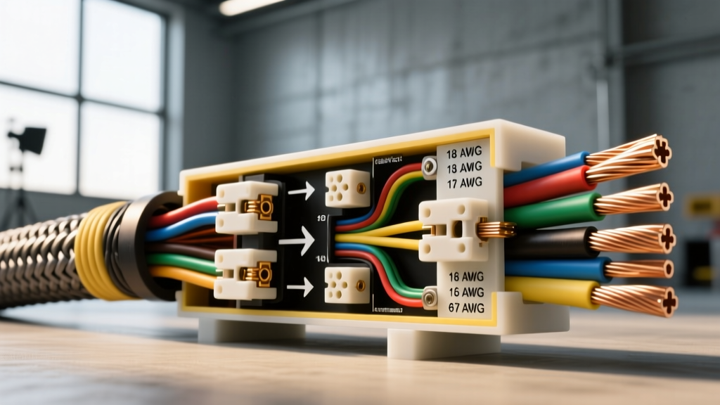
The Critical Role of Physical Dimensions in Automotive Wiring
When diagnosing automotive electrical faults, technicians often rely heavily on multimeters, oscilloscopes, and wiring schematics. However, a vast majority of intermittent faults, terminal push-outs, and localized voltage drops stem from a fundamental misunderstanding of physical wire dimensions. Converting wire gauge to inches is not merely an academic exercise; it is a critical diagnostic step when verifying terminal crimp depths, seal cavity clearances, and proper strip lengths in high-vibration environments.
Automotive primary wire standards, such as SAE J1128, dictate strict tolerances for conductor diameter and insulation thickness. Whether you are building a custom engine harness for an LS-swap or troubleshooting a failing fuel pump circuit on a heavy-duty truck, knowing the exact measurements in inches ensures that your wire matches the terminal barrel and weather seals perfectly. A mismatch of just a few thousandths of an inch can result in moisture ingress, increased electrical resistance, and catastrophic thermal failure.
Wire Gauge to Inches Conversion & Crimp Specification Chart
The following reference table provides the exact nominal conductor diameter in inches, the recommended wire strip length in inches, and the target crimp height (in inches) for standard open-barrel automotive terminals (such as those used in Delphi Weather-Pack and Metri-Pack series connectors).
| AWG Size | Conductor Diameter (Inches) | Cross-Section (Circular Mils) | Strip Length (Inches) | Target Crimp Height (Inches) | Common Automotive Application |
|---|---|---|---|---|---|
| 18 AWG | 0.0403" | 1,624 | 0.180" - 0.220" | 0.045" - 0.055" | Injector circuits, ECU sensors, CAN-bus |
| 16 AWG | 0.0508" | 2,583 | 0.200" - 0.250" | 0.060" - 0.070" | Lighting circuits, relay coils, horn |
| 14 AWG | 0.0641" | 4,107 | 0.220" - 0.280" | 0.075" - 0.085" | Power windows, seat motors, wipers |
| 12 AWG | 0.0808" | 6,530 | 0.250" - 0.310" | 0.095" - 0.110" | Fuel pump power, ignition coils, ABS |
| 10 AWG | 0.1019" | 10,380 | 0.300" - 0.375" | 0.120" - 0.140" | Cooling fans, high-amperage relays, main power feeds |
Step-by-Step Troubleshooting Flow: Physical Fitment & Voltage Issues
When a circuit exhibits high resistance or physical degradation, follow this step-by-step troubleshooting flow to verify that your wire gauge to inches conversions align with the physical hardware.
Step 1: Verify Insulation Outer Diameter vs. Seal Cavity
Symptom: Terminal push-out or moisture corrosion inside a sealed connector (e.g., Deutsch DT or Delphi Weather-Pack).
Diagnosis: Automotive wire comes in different insulation profiles. Standard GXL wire has a thicker insulation wall than TXL (extra-thin-wall). If you are using 14 AWG GXL, the outer diameter might measure 0.095 inches, which will bind or tear the rear silicone seal of a standard Weather-Pack cavity designed for a maximum of 0.085 inches.
Action: Measure the outer diameter of the insulated wire using digital calipers. If the measurement in inches exceeds the connector manufacturer's specified seal cavity maximum, you must switch to TXL wire or step down to a higher AWG (thinner wire) while paralleling the run to maintain ampacity.
Step 2: Measure Strip Length to the Nearest 1/16th Inch
Symptom: Intermittent voltage drop across a crimped connection under heavy load (e.g., cooling fan engaging).
Diagnosis: If the wire strip length is too short, the terminal's conductor wings will crimp onto the insulation jacket rather than the bare copper strands. If the strip length is too long, bare copper will extend past the terminal barrel. This exposed copper (even just 0.050 inches) is highly susceptible to galvanic corrosion and strand splay, which reduces the effective cross-sectional area.
Action: Use a calibrated wire stripper set to the exact strip length in inches specified in the chart above. For 12 AWG wire powering a 15-amp fuel pump, the strip length must be precisely 0.280 inches to ensure the insulation stop rests exactly against the wire jacket without biting into the copper strands.
Step 3: Calculate Short-Distance Voltage Drop (Inches vs. Feet)
Symptom: A high-current component like a starter solenoid or glow plug relay fails to engage, despite showing 12.6V at the battery.
Diagnosis: While standard voltage drop calculators use feet, heavy automotive circuits often fail over distances measured in inches. A poor crimp or a corroded ring terminal on a 2 AWG cable (0.2576 inches in diameter) can introduce 0.05 ohms of resistance. Over just 12 inches of cable, this localized resistance will cause a massive voltage drop under a 200-amp starter load.
Action: Perform a loaded voltage drop test directly across the crimp joint. Place your multimeter probes on the bare wire (just behind the crimp barrel) and the mating stud. A drop greater than 0.10V across a connection less than 6 inches long indicates a failed crimp or oxidation, requiring immediate re-termination.
Decision Tree: Diagnosing Crimp & Fitment Failures
Use the following decision tree when inspecting a failed automotive terminal:
- Is the wire pulling out of the terminal under light tension?
- Yes: Check conductor diameter. Did you use 18 AWG (0.040") in a terminal designed for 16 AWG (0.050")? Fix: Use the correct AWG or fold the wire back on itself to increase the crimp mass.
- No: Proceed to next step.
- Is the silicone weather seal torn or failing to seat?
- Yes: Measure the wire's outer insulation diameter in inches. Are you using standard PVC wire instead of cross-linked GXL/TXL? Fix: Switch to TXL wire to reduce outer diameter while maintaining the same AWG.
- No: Proceed to next step.
- Is the terminal overheating or showing signs of melting plastic?
- Yes: Measure the crimp height. Is it taller than the target specification (e.g., >0.110" for 12 AWG)? A tall crimp means low compression and high resistance. Fix: Adjust crimp die settings or replace the ratcheting crimp tool.
Real-World Case Study: LS-Engine Swap Injector Harness
During a custom GM LS-engine swap utilizing an aftermarket harness, a builder experienced random misfires on cylinders 2 and 6 under high RPM. The ECU was throwing P0202 and P0206 (Injector Circuit Malfunction) codes. The wiring diagram called for 18 AWG wire for the injector control circuits, utilizing EV1-style connectors.
Upon physical inspection, the builder had attempted to 'upgrade' the harness by using 16 AWG wire, assuming thicker wire would prevent voltage drop. However, the 16 AWG conductor diameter (0.0508 inches) was too large for the micro-crimp barrel of the EV1 female terminal, which is engineered specifically for 18 AWG to 20 AWG (0.0403" to 0.0320"). Because the wire was too thick, the terminal wings failed to close completely, leaving a massive air gap inside the crimp. Under the high-frequency pulsing of the injector driver, this poor physical connection acted as a capacitor and resistor, distorting the square-wave signal from the ECU.
The Fix: The builder stripped back the harness, verified the wire gauge to inches specifications, and re-pinned the harness using proper 18 AWG TXL wire (Dark Green with a White stripe for Cylinder 2, and Light Blue with a White stripe for Cylinder 6). The crimp height was verified at 0.050 inches using a digital micrometer. The misfires were entirely eliminated, proving that in low-amperage, high-frequency ECU circuits, physical fitment supersedes ampacity upgrades.
Authoritative Sources & Further Reading
Accurate automotive wiring requires adherence to strict engineering standards. The data and troubleshooting methodologies provided in this guide are derived from the following industry-standard resources:
- SAE International - J1128: Low Tension Primary Cable - The definitive standard for automotive wire insulation thickness, temperature ratings, and conductor diameter tolerances.
- TE Connectivity / Deutsch DT Series Assembly Instructions - Provides exact strip lengths in inches and crimp die settings for sealed automotive connectors.
- Delphi Packard Electrical Systems - Weather-Pack Design Guide - Details the seal cavity dimensions and insulation diameter limits for preventing terminal push-out and moisture ingress.
By treating physical dimensions with the same respect as electrical continuity, automotive technicians and fabricators can build harnesses that survive the extreme thermal and vibrational cycles of modern engine bays.