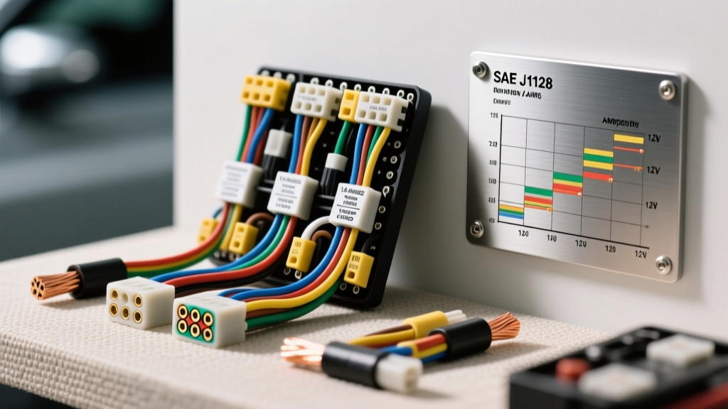
The Core Formula: How to Know What Gauge Wire to Use
Determining the correct American Wire Gauge (AWG) for automotive applications requires more than a generic household wiring chart. When automotive technicians and DIYers ask how to know what gauge wire to use, the answer relies on three critical variables: maximum continuous amperage, total circuit length (positive and ground paths), and the ambient temperature of the routing environment. Using an undersized wire in a vehicle leads to excessive voltage drop, melted insulation, and potential electrical fires, while oversized wire adds unnecessary weight and makes routing through tight firewall grommets and connector housings difficult.
SAE J1128 vs. NEC: Why Household Charts Fail in Vehicles
The most common mistake in automotive wiring is referencing the National Electrical Code (NEC) ampacity tables. The NEC is designed for solid-core copper wire routed in open-air or conduit building environments. Automotive wiring, governed by the SAE J1128 Standard for Low Tension Primary Cable, utilizes finely stranded copper to withstand constant vibration. Furthermore, automotive wire is often bundled tightly inside corrugated loom and routed through engine bays where ambient temperatures routinely exceed 105°C (221°F). Therefore, automotive AWG ampacity ratings must be heavily derated compared to residential wiring to account for thermal bundling and high heat exposure.
Automotive AWG Ampacity Reference Chart (SAE J1128)
The following chart outlines standard cross-linked (GXL/TXL) automotive wire capacities. These ratings assume a 125°C temperature rating and a standard engine bay ambient temperature of 50°C. If routing near exhaust manifolds or turbochargers, you must use high-temperature silicone or fiberglass-sleeved wire and increase the gauge by one size.
| AWG Size | Max Amps (Single Wire in Free Air) | Max Amps (Bundled in Loom/Engine Bay) | Resistance (Ohms per 1,000 ft) | Common Automotive Application |
|---|---|---|---|---|
| 18 AWG | 16A | 10A | 6.510 | ECU sensor signals, LED indicator lights, CAN-bus lines |
| 16 AWG | 22A | 14A | 4.094 | Horn relays, interior dome lights, fuel injector power feeds |
| 14 AWG | 32A | 20A | 2.575 | Headlight circuits, power window motors, cigarette lighter sockets |
| 12 AWG | 41A | 28A | 1.619 | Fuel pump primary feeds, aftermarket amplifiers (up to 200W), cooling fans |
| 10 AWG | 55A | 39A | 1.018 | Ignition switch main feeds, high-amp lighting relays, ABS module power |
| 8 AWG | 73A | 53A | 0.641 | Starter solenoid control, high-output alternator sensing, winch controls |
| 6 AWG | 95A | 70A | 0.403 | Main battery to fuse block feeds, heavy-duty off-road light bars |
| 4 AWG | 125A | 92A | 0.253 | High-output alternator charging cables, main inverter feeds |
| 1/0 AWG | 210A | 160A | 0.100 | Battery relocation kits, starter motor primary cables, mega-fuse links |
Calculating Voltage Drop for Long Harness Runs
Ampacity is only half the equation. To truly understand how to know what gauge wire to use, you must calculate voltage drop. A wire might be thick enough to carry 30 amps without melting, but if the run is 25 feet long, the resistance will cause a significant voltage drop, starving the component of the 12+ volts it needs to operate efficiently. According to AutoShop 101 Basic Electrical Circuits guidelines, acceptable voltage drop in a 12V automotive system is less than 3% (0.42V) for sensitive ECU/sensor circuits, and less than 5% (0.70V) for lighting and accessory loads.
The Voltage Drop Formula
Use the following formula to calculate voltage drop ($V_D$):
$V_D = \frac{2 \times L \times I \times R}{1000}$
- L = Total length of the wire run in feet (positive AND ground paths combined)
- I = Current draw in Amps
- R = Resistance of the specific AWG wire per 1,000 feet (see chart above)
Case Study: Wiring a 40A Off-Road Light Bar via Relay
Let us apply these specifications to a real-world scenario. You are installing a 40A LED light bar on the roof rack of a 2018 Jeep Wrangler JK. The battery is in the engine bay, and the total wire run (from battery, through the firewall, up the A-pillar, to the roof, and back to chassis ground) is 22 feet. The system voltage when the engine is running is 14.4V.
Step 1: Select Wire Based on Ampacity
A 40A load requires a wire rated for at least 40A in a bundled environment. Looking at the SAE chart, 10 AWG is rated for 39A bundled, which is slightly under our 40A requirement. We must step up to 8 AWG wire, which handles 53A bundled safely.
Step 2: Calculate Voltage Drop for 8 AWG
- L = 22 feet
- I = 40 Amps
- R (8 AWG) = 0.641 Ohms/kft
$V_D = \frac{2 \times 22 \times 40 \times 0.641}{1000} = 1.12V$
A 1.12V drop on a 14.4V system is a 7.7% voltage drop. This exceeds the 5% maximum threshold, meaning the light bar will be dim and the 8 AWG wire will run warm. We must step up to 6 AWG wire.
Step 3: Recalculate with 6 AWG
- R (6 AWG) = 0.403 Ohms/kft
$V_D = \frac{2 \times 22 \times 40 \times 0.403}{1000} = 0.70V$
A 0.70V drop is exactly 4.8%, which falls safely under the 5% limit. Therefore, 6 AWG GXL wire is the correct engineering choice for this circuit.
Wire Insulation Types and Color Codes
Choosing the right gauge is useless if the insulation melts. Never use standard PVC wire (GPT) under the hood. Always specify Cross-Linked Polyethylene (XLPE) insulation.
- GXL (General Cross-Linked): Standard thickness, 125°C rating. Ideal for engine bay harnesses and chassis routing.
- TXL (Thin Cross-Linked): Thinner insulation, 125°C rating. Used for tight spaces, dashboard harnesses, and multi-pin ECU connectors.
- SXL (Special Cross-Linked): Thickest insulation, 125°C rating. Used for high-wear areas, battery cables, and heavy-duty truck chassis.
Standard Automotive Color Coding
While custom harnesses vary, adhering to SAE and OEM color standards prevents catastrophic miswiring during future diagnostics:
- Red: Constant +12V Battery Power (Unswitched)
- Yellow / Pink: Switched +12V (Ignition/Run/Start circuits)
- Black: Primary Chassis Ground
- Orange: CAN-High (High-speed data bus)
- Green / White: CAN-Low or specific sensor return signals
Connector Selection and Crimp Specifications
The most common failure point in an automotive circuit is not the wire itself, but the termination. For high-current circuits (above 10A), avoid open-barrel crimps and solder-only connections. Solder creates a rigid joint that will fatigue and snap under engine vibration.
Use closed-barrel copper crimp terminals with adhesive-lined polyolefin heat shrink. The adhesive melts and seals the wire strands, preventing moisture ingress and capillary action corrosion. When crimping, always use a ratcheting crimper calibrated for the specific AWG to ensure the terminal barrel is compressed to the exact millimeter specification, achieving a cold-weld gas-tight connection.
Common Wire Gauge Failure Modes & Troubleshooting
If a circuit is failing, use a digital multimeter (DMM) to diagnose these common gauge-related issues:
- Symptom: Component operates at full power when cold, but dims or shuts off after 10 minutes of use.
Cause: Wire gauge is too small, causing excessive resistance and heat buildup. As copper heats up, its resistance increases exponentially, compounding the voltage drop until the component starves. - Symptom: Fuse blows intermittently during engine cranking.
Cause: Voltage drops below 9V during starter engagement. To maintain wattage ($W = V \times I$), the component draws higher amperage, exceeding the fuse rating. Upgrading the wire gauge reduces resistance, maintaining higher voltage at the component during cranking. - Symptom: ECU throws intermittent sensor codes (e.g., O2 sensor heater circuit).
Cause: 18 or 20 AWG wire used for a high-draw heater circuit. The thin wire acts as a resistor, dropping voltage before it reaches the sensor, tricking the ECU into reading an open circuit.
By strictly following SAE J1128 ampacity derating, calculating voltage drop for total circuit length, and utilizing cross-linked insulation, you ensure safe, reliable, and professional-grade automotive electrical systems.