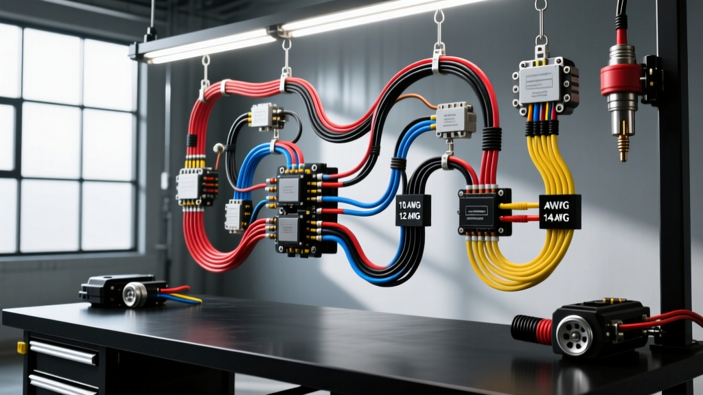
The Critical Role of Wire Gauge Measurements in Off-Road Mods
Upgrading a 2016-2023 Toyota Tacoma TRD Off-Road for overlanding requires more than just bolting on a winch and an LED roof bar. When integrating high-draw accessories like a 120W 40-inch LED light bar and dual 40W LED pods, the integrity of your electrical system hinges entirely on accurate wire gauge measurements. Many aftermarket wiring kits utilize undersized, copper-clad aluminum (CCA) wire that masquerades as pure copper. Failing to verify physical wire gauge measurements before routing harnesses through the firewall and chassis can lead to severe voltage drop, melted insulation, and catastrophic electrical fires. According to the SAE J1128 Low Tension Primary Cable Standard, automotive wire must withstand extreme thermal cycling and vibration, a benchmark that cheap import wires consistently fail to meet.
Project Scope: Tacoma Auxiliary Lighting & Winch Control
This reference guide focuses on a comprehensive auxiliary lighting and winch solenoid trigger upgrade for the 3rd Generation Toyota Tacoma. The project involves routing new harnesses from the engine bay fuse block to a centralized Bosch-style ISO relay block, and subsequently to the exterior lighting fixtures and Warn winch solenoid. The total continuous draw for the lighting circuit is approximately 16.6 Amps (200W total at 12V nominal). To ensure optimal performance and longevity, we must calculate voltage drop and select the correct American Wire Gauge (AWG) based on precise physical measurements.
The Science of Voltage Drop and Caliper Verification
The AWG system is logarithmic; a lower gauge number indicates a thicker wire with lower resistance. However, relying solely on the printed text on the wire jacket is a critical mistake in modern automotive modification. Unscrupulous manufacturers often print '12 AWG' on a jacket that contains 16 AWG CCA wire. To protect your investment, you must use digital calipers to take actual wire gauge measurements of the copper stranding diameter (excluding the insulation). Pure Oxygen-Free Copper (OFC) will measure true to spec, while CCA will often fall short and exhibit a silvery core when scratched.
For a 12V automotive lighting circuit, the maximum acceptable voltage drop is 3% (0.36V) for critical electronics and up to 10% (1.2V) for standard illumination. We use the following formula to calculate voltage drop based on your wire gauge measurements:
Voltage Drop = (2 x One-Way Length in Feet x Current in Amps x Resistance per 1000ft) / 1000
For example, using true 10 AWG OFC wire (1.02 ohms/kft) for a 15-foot run drawing 16.6 Amps yields a voltage drop of just 0.50V, well within acceptable limits for off-road LED drivers.
Wire Gauge Measurements & Ampacity Reference Chart
The following chart provides the exact physical dimensions and chassis-wiring ampacity ratings for standard OFC automotive primary wire. Use these baseline numbers to verify your wire gauge measurements with a micrometer or caliper before installation.
| AWG Size | Strand Count | Conductor Diameter (mm) | Conductor Diameter (in) | Max Amps (Chassis) | Resistance (Ohms/1000ft) |
|---|---|---|---|---|---|
| 10 AWG | 105 | 2.59 mm | 0.1019 in | 30 A | 1.02 |
| 12 AWG | 65 | 2.05 mm | 0.0808 in | 20 A | 1.62 |
| 14 AWG | 41 | 1.63 mm | 0.0641 in | 15 A | 2.58 |
| 16 AWG | 26 | 1.29 mm | 0.0508 in | 10 A | 4.09 |
| 18 AWG | 16 | 1.02 mm | 0.0403 in | 7 A | 6.51 |
Routing, Color Codes, and Pin Configurations
Proper color coding and pin assignment are non-negotiable for future troubleshooting. When integrating the new relay block and exterior fixtures, adhere to the following wiring schematic and connector standards. For high-vibration exterior connections, we exclusively recommend TE Connectivity Deutsch DT Series Connectors due to their silicone rear seals and integrated strain relief.
Main Power Feed (Battery to Relay Block)
- Wire Spec: 10 AWG OFC, Cross-Linked Polyethylene (XLPE) insulation.
- Color Code: Red (Power), Black (Ground).
- Routing: Through the factory Tacoma firewall grommet located behind the driver-side kick panel. Always apply silicone dielectric grease to the grommet to prevent tearing.
- Protection: Inline 20A ATO blade fuse located within 6 inches of the battery positive terminal.
Relay Trigger & Illumination Circuit
- Wire Spec: 16 AWG OFC for trigger, 18 AWG OFC for switch illumination.
- Color Code: Blue with White Stripe (12V Trigger from upfitter switch), Orange (Dash Illumination).
- Connector: Metri-Pack 280 series for tapping into the factory upfitter switch harness.
Deutsch DT Connector Pinout for LED Pods
Each 40W LED pod will terminate in a 2-pin Deutsch DT plug (DT06-2S-E004). The mating receptacle (DT04-2P-E004) will be housed in a weatherproof junction block near the grille.
- Pin 1 (Cavity 1): 12V+ Load from Relay Pin 87. (Red 14 AWG wire).
- Pin 2 (Cavity 2): Chassis Ground. (Black 14 AWG wire).
ISO Mini Relay Block Configuration
The project utilizes a standard Bosch-style 5-pin ISO mini relay to isolate the high-draw lighting circuit from the low-amperage cabin switch. The pin configuration on the relay block must be wired as follows:
- Pin 30 (Common Input): 10 AWG Red from Battery (Fused).
- Pin 87 (Normally Open Output): 10 AWG Red to LED Light Bar and Pods.
- Pin 86 (Coil Positive): 16 AWG Blue/White from Cabin Upfitter Switch.
- Pin 85 (Coil Ground): 16 AWG Black to dedicated chassis ground.
- Pin 87a (Normally Closed): Unused and capped with heat shrink.
Termination Standards and Torque Specifications
A wire is only as good as its termination. For all ring terminal connections, use adhesive-lined dual-wall polyolefin heat shrink. The internal thermoplastic adhesive melts and flows around the wire strands, creating a waterproof seal that prevents capillary action from drawing moisture under the insulation jacket.
- M8 Ground Ring Terminal to Chassis: Clean the mounting surface down to bare metal using a brass wire brush. Apply a thin layer of conductive anti-seize, torque to 15 Nm (11 lb-ft), and cover with liquid electrical tape.
- M6 Battery Terminal Connection: Torque to 8 Nm (5.9 lb-ft). Ensure the terminal is positioned on top of the factory OEM cables, not sandwiched between them, to maximize surface area contact.
- Crimping Tool: Use a ratcheting crimper calibrated for insulated terminals. A proper crimp should pass the 'pull test' (withstanding 40 lbs of tensile force) without the wire slipping.
Real-World Failure Modes: CCA vs. OFC and Chafing
When taking wire gauge measurements on failed aftermarket harnesses, we frequently find CCA wire that has oxidized internally. CCA (Copper Clad Aluminum) has a higher resistance than pure copper and is highly susceptible to galvanic corrosion when mated with copper terminals in the presence of moisture. This corrosion increases resistance, which generates heat, ultimately melting the relay block. Always demand OFC (Oxygen-Free Copper) wire from reputable suppliers like Ancor or Painless Performance.
Another common failure mode is chafing at the hood hinge or radiator support. The Tacoma's hood hinges create a severe pinch point during closure. Any wiring routed near the hinge must be encased in split-loom corrugated tubing and secured with T-clip fasteners to the factory harness points, maintaining at least 2 inches of clearance from moving components.
Expert Troubleshooting Decision Tree
When your auxiliary lighting or winch control circuit exhibits abnormal behavior, use this diagnostic tree to isolate the fault based on voltage drop and physical measurements.
- Symptom: LED Pods Flickering at High RPM
- Cause 1: Alternator AC Ripple due to a failing diode. Fix: Test alternator output with an oscilloscope; AC ripple should be < 50mV.
- Cause 2: Loose Metri-Pack 280 terminal at the relay block causing intermittent contact under vibration. Fix: Extract terminal with a removal tool, check for bent tangs, and re-seat until an audible 'click' is heard.
- Symptom: Winch Solenoid Clicks but Motor Doesn't Turn
- Cause 1: Severe voltage drop at the control circuit ground. Fix: Measure voltage between the battery negative post and the solenoid ground stud while the switch is engaged. A reading > 0.2V indicates a poor ground.
- Cause 2: Corroded factory battery-to-chassis ground strap. Fix: Remove, clean with a wire wheel, and reinstall the OEM M10 ground bolt to 45 Nm.
- Symptom: Upfitter Switch Illumination Flickers When Turn Signal is Used
- Cause 1: Backfeeding through a shared ground bus or improper tap into the turn signal circuit instead of a dedicated 12V illumination source. Fix: Reroute the 18 AWG Orange wire to the factory headlight switch illumination circuit (Pin 14 on the Tacoma integration relay).
Final Validation
Before sealing the firewall grommet and reassembling the Tacoma's interior kick panels, perform a final load test. Activate all auxiliary lighting simultaneously and use a digital multimeter to measure the voltage directly at the Deutsch DT connectors. According to Blue Sea Systems Circuit Sizing Guidelines, the voltage at the load should not drop below 11.8V with the engine idling (13.8V alternator output). By strictly adhering to accurate wire gauge measurements, utilizing OFC conductors, and following precise torque and crimping specifications, your overland rig will feature an electrical system that is as reliable and rugged as the vehicle itself.