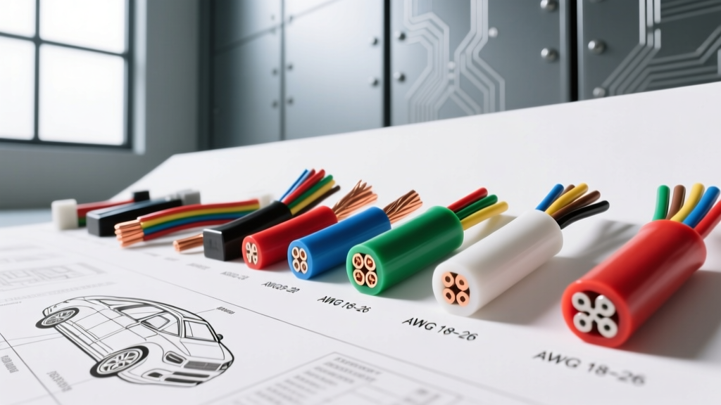
Introduction to Small Gauge Wire in Modern Automotive Networks
As automotive electrical architectures have transitioned from simple point-to-point power delivery to highly complex multiplexed networks, the reliance on small gauge wire has increased exponentially. Modern vehicles utilize dozens of microcontrollers communicating via Controller Area Network (CAN), Local Interconnect Network (LIN), and FlexRay protocols. These data circuits, along with low-current sensor references and actuator feedback loops, rarely draw more than a few milliamps. Consequently, automotive harness designers heavily specify small gauge wire—typically ranging from AWG 18 down to AWG 26—to reduce vehicle weight, minimize harness bulk, and lower copper costs.
However, working with thin-gauge automotive wiring requires a strict understanding of thermal derating, voltage drop limitations in 5-volt reference circuits, and specialized termination techniques. This technical reference outlines the specifications, applications, and diagnostic considerations for small gauge wire in modern automotive environments.
SAE J1128 vs. ISO 6722: Insulation Standards for Thin-Gauge Circuits
When sourcing or repairing small gauge wire, technicians must match the original equipment manufacturer (OEM) insulation specifications. The two primary standards governing automotive primary wire are SAE J1128 (predominantly North American) and ISO 6722-1 (Global/European/Asian).
Common Insulation Types for AWG 18-26
- TXL (Thin Wall, Cross-Linked): The most common North American standard for small gauge wire. TXL features a thin, cross-linked polyethylene insulation that withstands under-hood temperatures up to 125°C (257°F) while minimizing harness diameter.
- GXL (General Purpose, Cross-Linked): Slightly thicker insulation than TXL, offering superior abrasion resistance. Often used in AWG 18 and 20 where the wire may be routed near sharp chassis edges.
- AVSS (Asian Vehicle Standard, Super-thin): Common in Japanese and Korean vehicles (e.g., Toyota, Honda, Hyundai). AVSS insulation is exceptionally thin, making it ideal for the dense, high-pin-count connectors found in modern Asian engine control modules (ECMs).
- FLR9Y / FLRY (European Standard): PVC or fluoropolymer thin-wall wires used in German and European platforms, optimized for tight routing in dashboard and body control modules.
AWG 18 through 26 Technical Specification Chart
The following table details the physical and electrical characteristics of small gauge wire commonly found in automotive sensor and data circuits. Note that Engine Bay Ampacity assumes an ambient temperature of 125°C, which severely derates the current-carrying capacity compared to standard chassis wiring charts.
| AWG Size | Nominal Copper Area (mm²) | Max Resistance (Ω/1000ft @ 20°C) | Chassis Ampacity (25°C) | Engine Bay Ampacity (125°C) | Primary Use Case |
|---|---|---|---|---|---|
| 18 AWG | 0.82 | 6.385 | 16 A | 6.0 A | O2 Sensor Heaters, Injector Drivers, Relay Coils |
| 20 AWG | 0.52 | 10.15 | 11 A | 4.0 A | CAN High/Low Bus, ABS Wheel Speed Sensors |
| 22 AWG | 0.32 | 16.14 | 7 A | 2.5 A | 5V Sensor References, MAP/TPS Signal Returns |
| 24 AWG | 0.20 | 25.67 | 5 A | 1.5 A | LIN Bus, Interior Switch Multiplexing, Airbag Squibs |
| 26 AWG | 0.13 | 40.81 | 3 A | 0.8 A | Shielded Audio/Data Cables, Steering Angle Sensors |
Voltage Drop Calculations in 5-Volt Reference Circuits
One of the most critical aspects of troubleshooting small gauge wire is understanding voltage drop in low-current, high-impedance circuits. The Powertrain Control Module (PCM) provides a 5.0V reference to sensors like the Throttle Position Sensor (TPS), Manifold Absolute Pressure (MAP) sensor, and Accelerator Pedal Position (APP) sensor. These sensors typically draw less than 20 milliamps (0.020 Amps).
The Math Behind the Fault Code
Using Ohm's Law (V = I × R), let us calculate the voltage drop on a 15-foot run of AWG 22 small gauge wire (Total circuit length = 30 feet out and back).
- Current (I) = 0.020 A
- Resistance (R) = 16.14 Ω/1000ft × 30ft = 0.484 Ω
- Voltage Drop (V) = 0.020 A × 0.484 Ω = 0.00968 V
Under normal conditions, a drop of ~0.01V is negligible; the PCM reads 4.99V. However, if a connector terminal suffers from micro-fretting corrosion, it can introduce an additional 15 Ω of contact resistance. The new voltage drop becomes 0.30V. The PCM now reads 4.70V at the sensor. This discrepancy will trigger a rationality fault code (e.g., P0121 for TPS or P0106 for MAP), even though the wire itself is not broken. When diagnosing small gauge sensor circuits, always measure voltage drop under a simulated load rather than relying solely on continuity beep tests, which cannot detect high-resistance corrosion.
CAN Bus Architecture and OBD-II DLC Pinouts
High-speed CAN (ISO 11898-2) networks rely heavily on AWG 20 and AWG 22 twisted-pair small gauge wire. The physical layer requires a twisted pair to cancel out electromagnetic interference (EMI), typically maintaining 1 twist per inch. The nominal resistance between CAN High and CAN Low, measured at the OBD-II Data Link Connector (DLC) with the battery disconnected and modules asleep, should be exactly 60 ohms (two 120-ohm terminating resistors in parallel).
Standard OBD-II DLC Small Gauge Wire Pinout
| Pin | Function | Typical AWG | Common OEM Wire Colors | Protocol / Notes |
|---|---|---|---|---|
| 4 | Chassis Ground | 18 AWG | Black, Brown | Direct chassis tie-in |
| 5 | Signal Ground | 18 AWG | Black/White, Brown/White | PCM Logic Ground Reference |
| 6 | CAN High | 20 AWG | Green/White, Dark Green, Pink | ISO 11898-2 (HS-CAN) |
| 14 | CAN Low | 20 AWG | Green/Black, Light Blue, Purple | ISO 11898-2 (HS-CAN) |
| 16 | Battery Positive | 16 or 18 AWG | Red, Orange, Pink/White | Constant 12V (Fused) |
Note: Wire colors vary significantly by manufacturer. For example, GM GMLAN networks often use Light Blue/Black and Pink/Black, while Ford MS-CAN networks utilize White/Blue and White/Brown. Always consult vehicle-specific OEM service manuals before piercing or splicing data lines.
Termination and Crimping Standards for Micro-Terminals
Crimping small gauge wire requires precision. Standard heavy-duty crimpers will crush AWG 22-26 terminals, destroying the tension fingers and leading to intermittent connection loss. Automotive harnesses predominantly use open-barrel (F-crimp) terminals.
Common Connector Systems for Thin-Gauge Wire
- Delphi/Aptiv Metri-Pack 150 Series: The industry standard for AWG 18 through 22. Features a pull-to-seat design with a secondary lock (TPA). Requires a specific Metri-Pack crimp die to ensure the wire bellmouth and insulation crimp are formed correctly without shearing the thin copper strands.
- Molex MX150 and TE Connectivity Superseal 1.2: Designed for AWG 20 through 24. These are heavily sealed connectors used in under-hood sensor applications (e.g., camshaft position sensors, knock sensors). They feature pre-assembled silicone mat seals that grip the thin outer diameter of TXL/AVSS wire.
- TE Connectivity NanoMQS: Used for AWG 24 and 26 in highly dense interior modules, such as infotainment gateways and steering column control modules.
When repairing small gauge wire, always use a ratcheting crimp tool calibrated for the specific terminal series (such as the TE CERTI-CRIMP II or equivalent). A proper open-barrel crimp on AWG 22 wire should exhibit a visible 'wire brush' effect (bellmouth) at the front of the terminal, ensuring the copper strands are fully engaged without being cut by the terminal edges.
Troubleshooting High-Resistance Faults and 'Green Rot'
Small gauge wire is highly susceptible to a phenomenon colloquially known as 'green rot'—the oxidation of copper strands beneath the insulation. This occurs when moisture enters a damaged connector seal or a poorly sealed splice.
Capillary Action and Harness Wicking
Because the copper strands in AWG 20-26 wire are incredibly fine (often 19-strand or 26-strand tinned copper), capillary action can draw moisture several feet up into the wiring harness if the wire is routed downward from a sensor to an ECU. This wicking effect causes internal corrosion that cannot be seen from the outside. The insulation may look pristine, but the internal resistance of the small gauge wire will spike, causing signal degradation on high-impedance circuits like oxygen sensor signal lines or piezoelectric knock sensors.
Diagnostic Best Practices
- Avoid T-Pin Backprobing: Never use steel T-pins or paperclips to backprobe small gauge wire terminals (like Metri-Pack 150). The hardened steel will spread the beryllium-copper tension fingers, permanently ruining the terminal's grip and guaranteeing a future intermittent fault. Use dedicated, thin-gauge backprobe pins or breakout boxes.
- Drip Loops: When repairing or routing small gauge wire to undercarriage sensors (e.g., ABS wheel speed or ride height sensors), always create a 'drip loop' before the wire enters the connector cavity. This ensures gravity pulls moisture away from the terminal seal.
- Shake Testing: Intermittent faults in thin-gauge data circuits are often caused by a single broken copper strand inside the insulation. With the engine running and a scan tool monitoring live CAN data or sensor PID values, vigorously shake the harness. A sudden drop in the 5V reference or a spike in CAN bus error frames will isolate the exact location of the internal wire fracture.