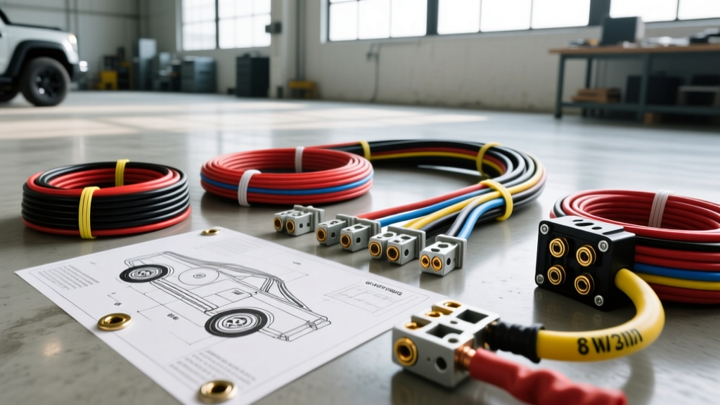
Why the Right Round Wire Gauge is Critical for Winch Installations
When upgrading a 4x4 recovery system or installing a heavy-duty electric winch, selecting the proper round wire gauge is the single most critical factor in the entire electrical build. Winches routinely draw between 300 and 550 amps under maximum load. If your cabling is undersized, you will experience severe voltage drop, sluggish winch performance, and potentially catastrophic insulation melt-downs. Unlike flat copper braided straps which are strictly meant for short, static grounding applications, a flexible, multi-strand round wire gauge is engineered to handle high-amperage DC current while enduring the constant vibration, chassis flex, and harsh environmental conditions inherent to off-road vehicles.
In this practical installation guide, we will walk through the exact process of calculating, routing, and terminating the correct round wire gauge for a standard 4-post solenoid winch system. We will focus on a 12,000-lb winch setup using 2 AWG ultra-flexible stranded copper, adhering to SAE J1128 low-tension primary cable standards for under-hood automotive applications.
Calculating Voltage Drop and Selecting Your Round Wire Gauge
Automotive electrical systems operate on a nominal 12.6V DC baseline. To ensure your winch motor receives adequate voltage (preventing premature contactor failure and motor overheating), the total voltage drop across the entire circuit must not exceed 0.5 volts under peak load. The physical length of the cable run and the peak amperage draw dictate the minimum round wire gauge you must use.
Below is a reference chart for selecting the appropriate round wire gauge based on winch capacity and total cable length (measured one-way from the battery to the solenoid, and solenoid to the winch motor).
| Winch Capacity (lbs) | Peak Amp Draw | Total Cable Run (One-Way) | Recommended Round Wire Gauge | Strand Count (Ultra-Flex) |
|---|---|---|---|---|
| 8,000 - 9,500 | 350A - 400A | Up to 8 feet | 4 AWG | 1,064 Strands |
| 10,000 - 12,000 | 400A - 450A | Up to 10 feet | 2 AWG | 1,330 Strands |
| 12,000 - 16,500 | 450A - 550A | Over 10 feet | 1/0 AWG | 2,109 Strands |
Note: Always round up to the next available round wire gauge if your cable run exceeds the recommended length or if your vehicle operates primarily in extreme cold climates, which increases copper resistance.
Step-by-Step Installation: Routing and Terminating 2 AWG Round Wire
Step 1: Battery Disconnect and Chassis Preparation
Before cutting any wire, disconnect the negative battery terminal and isolate it with a non-conductive cap. Clean the chassis grounding point where the winch ground will terminate. Use a wire brush to remove paint, rust, and undercoating down to bare metal. Apply a light coating of dielectric grease after securing the ground to prevent galvanic corrosion.
Step 2: Routing the Positive and Negative Cables
Measure and cut your 2 AWG red (positive) and black (negative) round wire. When routing through the engine bay, maintain a strict minimum clearance of 6 inches from the exhaust manifold, turbocharger downpipe, and steering shaft U-joints. Secure the round wire gauge every 12 to 18 inches using UV-resistant nylon cable ties or stainless steel P-clamps with rubber cushioning. Wrap the cables in split-loom tubing or braided TechFlex sleeving to protect against abrasion from chassis vibration and debris impact.
Step 3: Precision Stripping and Hydraulic Crimping
Terminating heavy-gauge round wire requires specialized tools. Do not use standard pliers or hammer-crimpers for 2 AWG or larger wire.
- Use a specialized heavy-gauge wire stripper to remove exactly 5/8" of insulation from the end of the round wire. Avoid nicking the outer copper strands, as this reduces the cross-sectional area and creates a localized hot spot.
- Slide a piece of 3:1 adhesive-lined marine heat shrink over the wire before inserting the stripped end into a tinned copper 3/8" ring terminal.
- Insert the terminal into a hydraulic hex-crimp tool fitted with the correct AWG die. Perform the crimp until the tool's pressure relief valve engages, ensuring a gas-tight, cold-weld connection.
- Apply heat to the adhesive shrink until the sealant oozes from the edges, creating a waterproof barrier against capillary action and corrosion.
Step 4: Solenoid Wiring and Trigger Circuit Configuration
Most high-amperage winches utilize a 4-post contactor (solenoid). Connect your heavy-gauge round wire as follows:
- Post A (Top Left): Positive 2 AWG from the main battery.
- Post B (Bottom Left): Positive 2 AWG to the winch motor positive terminal.
- Post C (Top Right): Negative 2 AWG from the chassis ground or battery negative.
- Post D (Bottom Right): Negative 2 AWG to the winch motor negative terminal.
Torque Specifications and Final Validation
Improper torque on high-current lugs is a leading cause of electrical fires. The contactor nuts must be tightened to 10-12 ft-lbs using a calibrated torque wrench. Over-tightening can strip the fine threads on the solenoid posts or crack the bakelite housing, while under-tightening will increase electrical resistance and cause arcing under load. The main battery terminal clamp should be torqued to 8-10 ft-lbs.
Common Failure Modes and Troubleshooting
Even with the correct round wire gauge, installations can suffer from hidden faults. Use a digital multimeter to perform a loaded voltage drop test. Have an assistant spool the winch in under a load (such as wrapping the line around a tree trunk with a snatch block for resistance).
- Symptom: Winch clicks but does not turn. Cause: Voltage drop exceeding 2V across the main positive cable. Fix: Check for loose crimps or undersized round wire gauge.
- Symptom: Solenoid melts or fuses together. Cause: High resistance at the lug connection due to corrosion or lack of adhesive heat shrink. Fix: Cut back the wire, re-crimp, and seal properly.
- Symptom: Winch operates only in one direction. Cause: Faulty trigger wire or corroded solenoid coil connection. Fix: Test the 10 AWG trigger circuit for 12V during switch actuation.