The Direct Answer: What Gauge Is Phone Wire?
When custom fabricators, alarm installers, and DIY telemetry enthusiasts first ask, "what gauge is phone wire," they are typically looking for a thin, flexible conductor to route through tight dashboard cavities or steering columns. Standard indoor telecommunications cabling—commonly terminated with RJ11 or RJ14 connectors—is almost universally manufactured in 22, 24, or 26 AWG (American Wire Gauge). The most common residential and commercial phone wire is 24 AWG solid copper, which features a bare conductor diameter of 0.0201 inches (0.51 mm) and a resistance of approximately 25.67 ohms per 1,000 feet at 20°C.
While 24 AWG is perfectly adequate for low-voltage, low-current analog voice signals or basic DSL data transmission in a climate-controlled, stationary building, it is fundamentally incompatible with the harsh environment of a vehicle. Understanding the physical and chemical differences between telecom wire and automotive-grade wire is critical before you attempt to use leftover phone wire for your next 12V modification project.
The Fatal Flaw of Telecom Wire in Vehicle Modifications
The primary reason phone wire fails in automotive applications is not its gauge, but its stranding configuration. Phone wire utilizes a solid copper core. In a stationary wall, solid core wire is cheap and easy to punch down into keystone jacks. However, a vehicle is a high-vibration, high-shock environment. When solid copper wire is subjected to the constant harmonic vibrations of an internal combustion engine, chassis flex, and road impacts, the copper undergoes a metallurgical process called work hardening.
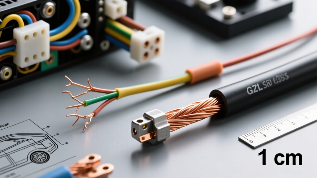
As the solid core micro-bends over thousands of miles, it becomes brittle and eventually snaps inside the insulation. This creates an intermittent open circuit that is notoriously difficult to diagnose with a standard multimeter, as the wire may show continuity on the bench but fail under the vibration of a running engine. For any automotive modification—whether you are wiring a low-current LED toggle switch, a GPS tracker, or a CAN bus data logger—you must exclusively use stranded wire. A standard automotive 22 AWG wire consists of 19 individual strands of 34 AWG copper, allowing the wire to flex infinitely without fatiguing the metal.
Material Science: PVC vs. Cross-Linked Polyethylene (XLPE)
The second major failure point of phone wire in automotive mods is the insulation jacket. Standard telecom wire uses a basic Polyvinyl Chloride (PVC) jacket. PVC is rated for a maximum continuous operating temperature of roughly 60°C to 75°C (140°F to 167°F). In an engine bay, or even behind a dashboard exposed to summer sunlight, ambient temperatures can easily exceed 80°C, and heat-soak from exhaust headers or heater cores can push localized temperatures well over 100°C. Under these conditions, PVC insulation softens, melts, and shrinks back from the conductor, exposing bare wire to grounded metal chassis components and causing dead shorts.
Automotive modifications require wire that meets SAE J1128 specifications. The industry standard for thin-wall automotive wire is GXL (Cross-Linked Polyethylene) or TXL. The cross-linking process alters the molecular structure of the plastic, transforming it into a thermoset material that will not melt or flow even when exposed to temperatures up to 125°C (257°F). Furthermore, GXL is highly resistant to automotive fluids, including gasoline, diesel, oil, and battery acid, whereas standard phone wire PVC will degrade rapidly upon contact with hydrocarbons.
Specification Chart: Telecom vs. Automotive GXL
| Specification | Standard 24 AWG Phone Wire | 22 AWG Automotive GXL |
|---|---|---|
| Conductor Type | Solid Core (1 strand) | Stranded (19 x 34 AWG) |
| Conductor Diameter | 0.0201 in (0.51 mm) | 0.030 in (0.76 mm) |
| Insulation Material | PVC (Polyvinyl Chloride) | XLPE (Cross-Linked Polyethylene) |
| Max Temp Rating | 75°C (167°F) | 125°C (257°F) |
| Resistance (per 1k ft) | ~25.67 Ohms | ~16.14 Ohms |
| Vibration Resistance | Poor (Work-hardens and snaps) | Excellent (High flex life) |
| Chemical Resistance | Low (Degrades with oil/gas) | High (Automotive fluid resistant) |
Upgrade Project: CAN Bus Telemetry and Data Logging
A common modification where DIYers are tempted to use thin phone wire is the installation of a CAN bus data logger (such as an AEM CD-7, Haltech IC-7, or a simple Raspberry Pi-based telemetry node). Because CAN High and CAN Low data lines only carry milliamps of current, a thin 22 or 24 AWG wire is electrically sufficient. Furthermore, CAN bus requires a twisted pair configuration to reject common-mode electromagnetic interference (EMI) from the alternator and ignition coils. Since Cat3 or Cat5 phone/network wire is already twisted, it seems like the perfect shortcut.
However, using solid-core telecom wire for a CAN bus tap will inevitably lead to communication dropouts, Check Engine Lights, and limp-mode events. Instead, you must purchase automotive-grade twisted pair cable utilizing 22 AWG GXL stranded conductors. When tapping into the vehicle's OBD-II port for a telemetry upgrade, you must follow strict pinout protocols and use proper splicing techniques to maintain the network's 120-ohm characteristic impedance.
OBD-II Port Pinout for Data Mods
- Pin 6 (CAN High): Typically Yellow or Green/White. Carries the dominant/recessive high signal.
- Pin 14 (CAN Low): Typically Green or Blue/White. Carries the dominant/recessive low signal.
- Pin 16 (Battery +): 12V constant power. Requires at least 18 AWG GXL and an inline 5A fuse for your logger.
- Pins 4 & 5 (Chassis/Signal Ground): Must be tied together and grounded to the vehicle chassis using a clean, paint-free ring terminal.
When splicing your 22 AWG GXL twisted pair into the OBD-II harness, do not use generic 'vampire' T-taps. These pierce the insulation, expose the copper to moisture, and inevitably cut through thin stranded wires. Instead, strip the wires, use a proper Western Union splice (or a solder-seal heat shrink splice), and re-twist the pigtail tightly (at least 1 twist per inch) to maintain EMI rejection.
Termination: Why Standard Crimps Fail on Solid Core
If you have already routed phone wire through your firewall and are attempting to terminate it, you will quickly discover that standard automotive terminals (like Delphi/Aptiv Weather-Pack or open-barrel F-crimps) are entirely incompatible with solid core wire. Automotive crimp terminals are engineered to compress around the strands of a wire, creating a cold-weld that is mechanically stronger than the wire itself. The terminal's wire wings are designed to bite into stranded copper.
When you attempt to crimp an open-barrel terminal onto solid 24 AWG phone wire, the terminal's wings will simply scrape against the smooth solid core, failing to achieve a mechanical lock. Under the slightest tension or vibration, the wire will pull out of the connector. If you must terminate solid wire in a pinch, you are required to use closed-barrel, insulated ring terminals designed specifically for solid conductors, and you must use a ratcheting crimper with a hex-indent die. However, the only true professional solution is to pull the phone wire out and replace it with Aptiv-compliant stranded GXL wire.
Summary and Best Practices
To summarize, while the answer to "what gauge is phone wire" is usually 24 AWG, its solid-core construction and low-temperature PVC jacket make it entirely unsuitable for automotive modifications. Whether you are wiring a low-current alarm trigger, a CAN bus telemetry module, or dashboard LED indicators, always select 20 to 22 AWG stranded GXL or TXL wire. This ensures your modification will withstand the thermal extremes, chemical exposures, and harmonic vibrations inherent to the automotive environment, providing a reliable, factory-quality electrical connection that will last the life of the vehicle. For further reading on proper wire sizing and voltage drop calculations, consult standard cable specification documentation and adhere strictly to SAE J1128 guidelines.