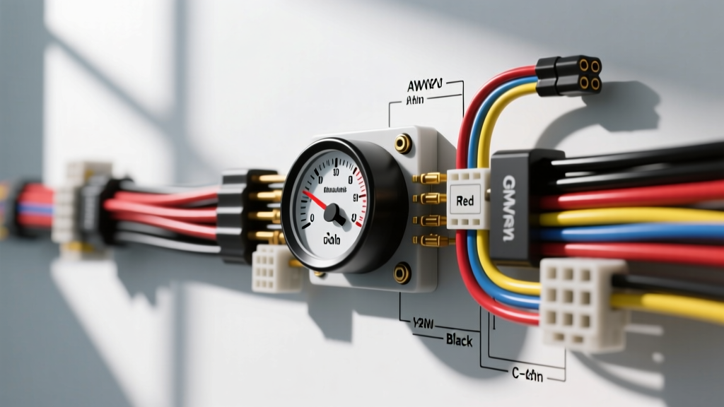
Introduction to Fuel Level Sender Circuits
The fuel gauge circuit is one of the most fundamental yet frequently misunderstood electrical systems in an automobile. Unlike high-current circuits that power fuel pumps or cooling fans, the fuel gauge wire carries a low-current analog signal from a variable resistor (potentiometer) located inside the fuel tank to the instrument cluster. Because the circuit relies on precise resistance measurements to determine the float arm's position, the integrity, gauge, and routing of the fuel gauge signal wire are critical. Even minor corrosion or improper wire sizing can introduce parasitic resistance, leading to inaccurate fuel readings, erratic gauge behavior, or the illumination of diagnostic trouble codes (DTCs) in modern OBD-II vehicles.
Fuel Gauge Wire AWG and Ampacity Specifications
When selecting or replacing fuel gauge wire, automotive technicians often mistakenly prioritize ampacity. However, a standard analog fuel level sender draws a negligible amount of current. Older bimetallic thermal gauges typically draw between 100mA and 150mA, while modern stepper-motor-driven instrument clusters draw less than 50mA on the signal reference circuit. Therefore, the wire does not need to handle high thermal loads.
Why 18 AWG to 20 AWG is the OEM Standard
Despite the low current draw, OEM manufacturers universally specify 18 AWG (0.82mm²) or 20 AWG (0.52mm²) wire for fuel level signal circuits. This sizing is dictated by mechanical durability and voltage drop mitigation rather than ampacity. Wires routed beneath the vehicle chassis are subjected to extreme vibration, road debris, moisture, and thermal cycling. Anything smaller than 20 AWG (such as 22 AWG or 24 AWG) is highly susceptible to copper strand fatigue and breakage inside the insulation jacket when subjected to chassis vibration.
According to SAE J1128 standards for low-tension primary cable, 18 AWG cross-linked polyethylene (XLPE) insulated wire is the preferred choice for underbody routing. XLPE offers superior resistance to abrasion, chemicals (including gasoline and road salts), and high temperatures compared to standard PVC insulation. When replacing damaged fuel gauge wire, always use SAE J1128 compliant GXL or TXL wire to ensure the insulation does not melt if routed near exhaust components.
OEM Fuel Sender Resistance Ranges & Wire Configurations
The most critical aspect of fuel gauge wiring is matching the instrument cluster's expected resistance range. The fuel gauge wire simply acts as a bridge; if the resistance of the sender does not match the gauge's internal calibration, the reading will be inverted or skewed. Below is the definitive reference chart for common OEM and aftermarket fuel sender resistance ranges.
| Manufacturer / Application | Empty Resistance (Ohms) | Full Resistance (Ohms) | Typical Signal Wire Color |
|---|---|---|---|
| General Motors (Pre-1997) | 0 Ω | 90 Ω | Purple |
| General Motors (1997-Present) | 40 Ω | 250 Ω | Purple / Purple-White |
| Ford Motor Company | 10 Ω | 180 Ω | Yellow/White Stripe |
| Chrysler / Dodge / Jeep | 22 Ω | 160 Ω | Dark Green/Red Stripe |
| VDO / European Aftermarket | 240 Ω | 33 Ω | Green (Often labeled 'T') |
| Stewart Warner / Standard Aftermarket | 240 Ω | 33 Ω | Sender Terminal 'S' |
Note: Never splice a Ford 10-180 ohm sender into a GM 0-90 ohm gauge without an inline signal converter or interface module. The gauge will read completely backwards and may trigger a low-fuel warning chime continuously.
Standard Wire Color Codes and Pinouts
Identifying the correct fuel gauge wire within a multi-pin fuel pump module connector is essential for diagnostics. Modern vehicles utilize a single harness connector at the top of the fuel tank that houses the fuel pump power, fuel pump ground, fuel level signal, fuel level ground, and EVAP pressure sensor wires.
- General Motors (Silverado/Sierra 1999-2006): The fuel level signal is typically a Purple wire. Crucially, GM uses a dedicated Black wire for the sender ground. Do not assume the fuel tank chassis provides the ground.
- Ford (F-150 2004-2008): The signal wire is usually Yellow with a White stripe. The dedicated sender ground is Black with an Orange stripe.
- Chrysler (Ram 2002-2008): The signal wire is Dark Green with a Red stripe. The ground is Black.
Connector Types and Pin Separation
OEM fuel tank modules heavily rely on sealed connectors to prevent fuel vapor intrusion and moisture ingress. The most common connector families include the Delphi Packard Metripack 150 and Weather-Pack series for older vehicles, and the Molex MX150 sealed series for modern applications. When servicing these connectors, always use the proper terminal extraction tool. Prying terminals out with a pick will destroy the silicone weather seals, leading to capillary action that draws moisture directly into the fuel gauge wire crimp, causing rapid green-copper corrosion.
Modern Digitized Fuel Modules and CAN/LIN Bus Wiring
In vehicles manufactured after 2010, the traditional analog fuel gauge wire is rapidly disappearing. Instead of running a raw analog resistance signal 15 feet from the tank to the dashboard, modern architectures utilize a Fuel Pump Control Module (FPCM) or an integrated Body Control Module (BCM) node located at the fuel tank.
In these systems, the analog sender is read locally by a microchip inside the tank module. The data is then digitized and transmitted to the instrument cluster via a CAN-bus (Controller Area Network) or LIN-bus (Local Interconnect Network). The wires carrying this data are no longer measuring resistance; they are high-speed data lines. These require 22 AWG or 24 AWG shielded twisted-pair wire. Splicing a standard 18 AWG primary wire into a CAN-High or CAN-Low data line will alter the characteristic impedance of the network (which must remain at 120 ohms), resulting in bus communication failures and a dash full of warning lights. For deep-dive electrical diagnostics on modern networks, referencing Haynes electrical troubleshooting guides is highly recommended to map out multiplexed networks.
Troubleshooting Voltage Drop and Grounding Issues
The most common cause of erratic fuel gauge operation is not a faulty sender, but a compromised ground or excessive voltage drop on the signal wire. Because the circuit measures resistance, any additional resistance introduced by a bad connection is interpreted by the gauge as a change in fuel level.
The 'Floating Ground' Problem
A frequent mistake made by amateur mechanics is assuming the metal fuel tank or the fuel pump housing can serve as an electrical ground. Most modern fuel tanks are constructed of High-Density Polyethylene (HDPE) plastic. Even in vehicles with metal tanks, the tank is secured to the chassis using rubber-isolated mounting straps to prevent galvanic corrosion and reduce NVH (Noise, Vibration, and Harshness). This rubber isolation means the tank is electrically 'floating'. A dedicated ground wire must run from the sender unit, through the main harness, to a verified clean chassis ground point. If this dedicated ground wire corrodes, the circuit will seek a ground through the fuel lines or tank straps, resulting in a high-resistance path that causes the gauge to read lower than the actual fuel level.
Symptom-Cause-Fix Decision Tree
Use the following diagnostic tree when troubleshooting fuel gauge wire issues:
- Symptom: Gauge is pegged past 'Full' or reads completely empty (depending on OEM logic).
- Cause: Open circuit (broken signal wire or disconnected connector).
- Fix: Perform a continuity test from the cluster pin to the tank module pin. Repair broken 18 AWG wire using a sealed solder sleeve and heat shrink.
- Symptom: Gauge fluctuates wildly while driving or cornering.
- Cause: Fretting corrosion inside the connector pins or a failing wiper arm on the sender card.
- Fix: Inspect the Metripack/Weather-Pack terminals for spread pins. Apply dielectric grease and replace terminals if the grip is loose.
- Symptom: Gauge consistently reads 1/4 tank lower than actual.
- Cause: Voltage drop on the dedicated ground wire due to corrosion.
- Fix: Measure voltage drop across the ground wire with the ignition ON. A drop greater than 0.1V indicates a bad ground. Clean the chassis ground ring terminal or run a new 18 AWG ground wire.
Summary and Best Practices
Proper maintenance and repair of fuel gauge wiring require strict adherence to OEM specifications. Always utilize 18 AWG or 20 AWG XLPE-insulated wire for analog signal replacements, respect the specific resistance ranges of your vehicle's manufacturer, and never overlook the critical importance of a dedicated, isolated ground circuit. For further reading on aftermarket gauge installations and sender matching, the Autometer fuel level resource guide provides excellent visual references for bench-testing variable resistors before permanent installation.